

Thelio Prime (Parts & Repairs)
Many components in your Thelio Prime can be upgraded or replaced as necessary. The Thelio Prime is also known simply as the Thelio. This page uses photos of the the R5-N2 revision, which indicates:
- R5: The fifth AMD motherboard used in Thelio Prime.
- N2: Based on the second major revision of the Thelio Prime chassis.
Minor case details may vary based on the production date of the unit, but screw counts, general component locations, and other details should remain the same unless otherwise noted.
Power the machine off, switch off the power supply, and unplug all peripherals before working with any internal components.
Removing the side panels:
Section titled “Removing the side panels:”The side panels can be removed to access the internal components.
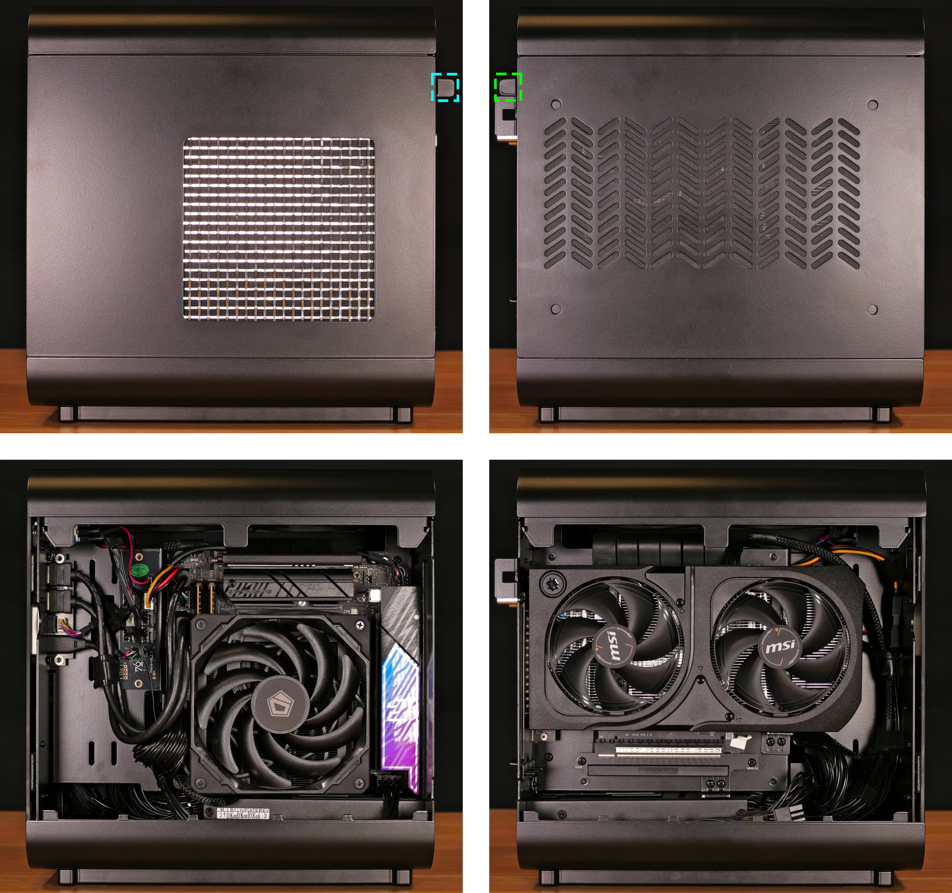
- The right side panel (with a mesh window) covers the motherboard, RAM, Thelio Io board, and front I/O.
- The right side panel (without a window) covers the GPU.
Tools required: Cross-head (Phillips) screwdriver (optional)
Time estimate: 2 minutes
Difficulty: Easy ●
Steps to remove the side panels:
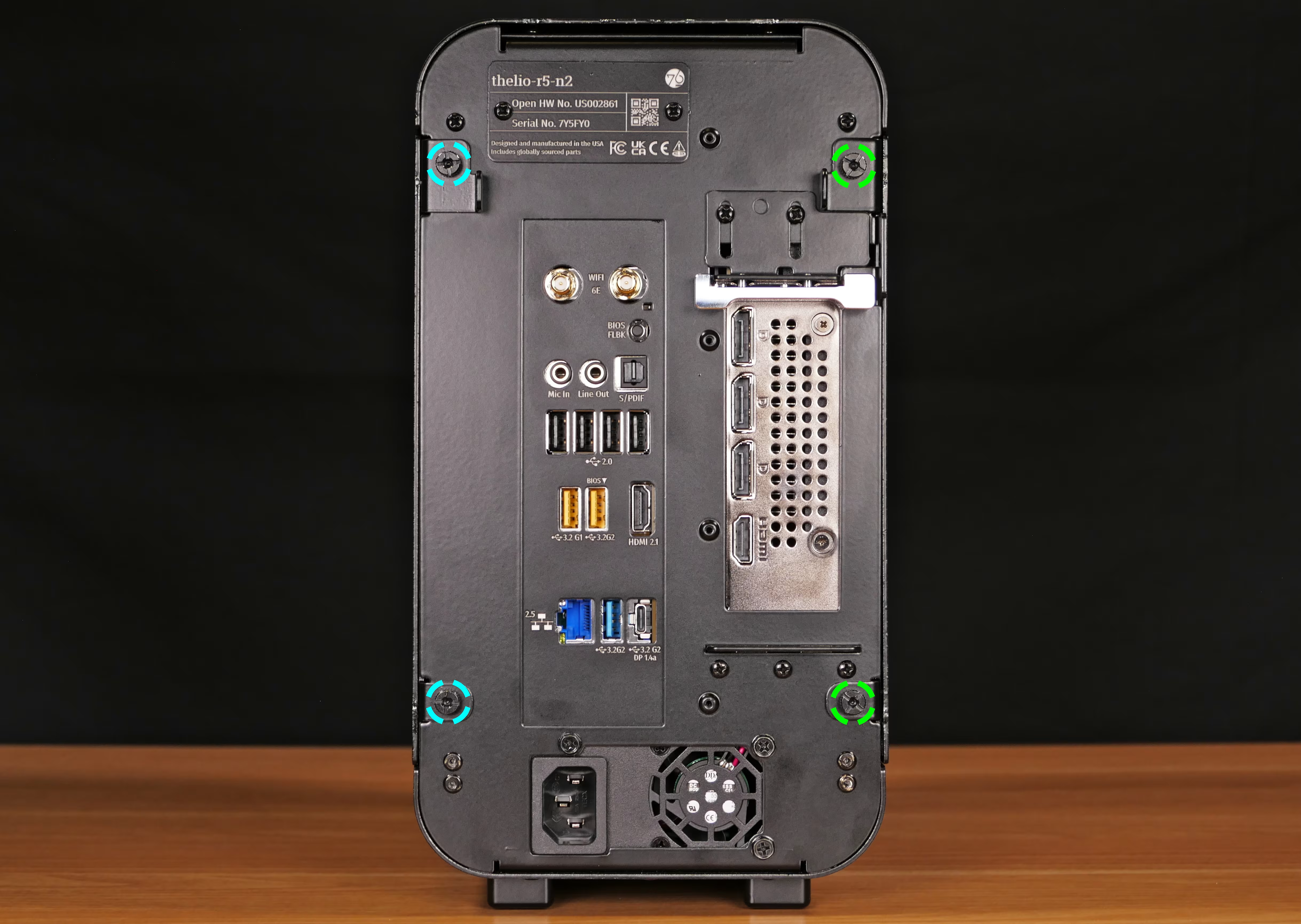
Section titled “Steps to remove the side panels:”- Remove the two back thumbscrews (per side) holding the side panels onto the machine.
- The right side panel’s screws are on the left when viewed from the back of the machine, highlighted cyan above.
- The left side panel’s screws are on the right when viewed from the back of the machine, highlighted green above.
- Starting from the tab at the upper back, pull each side panel off of the machine.
Removing the front glass:
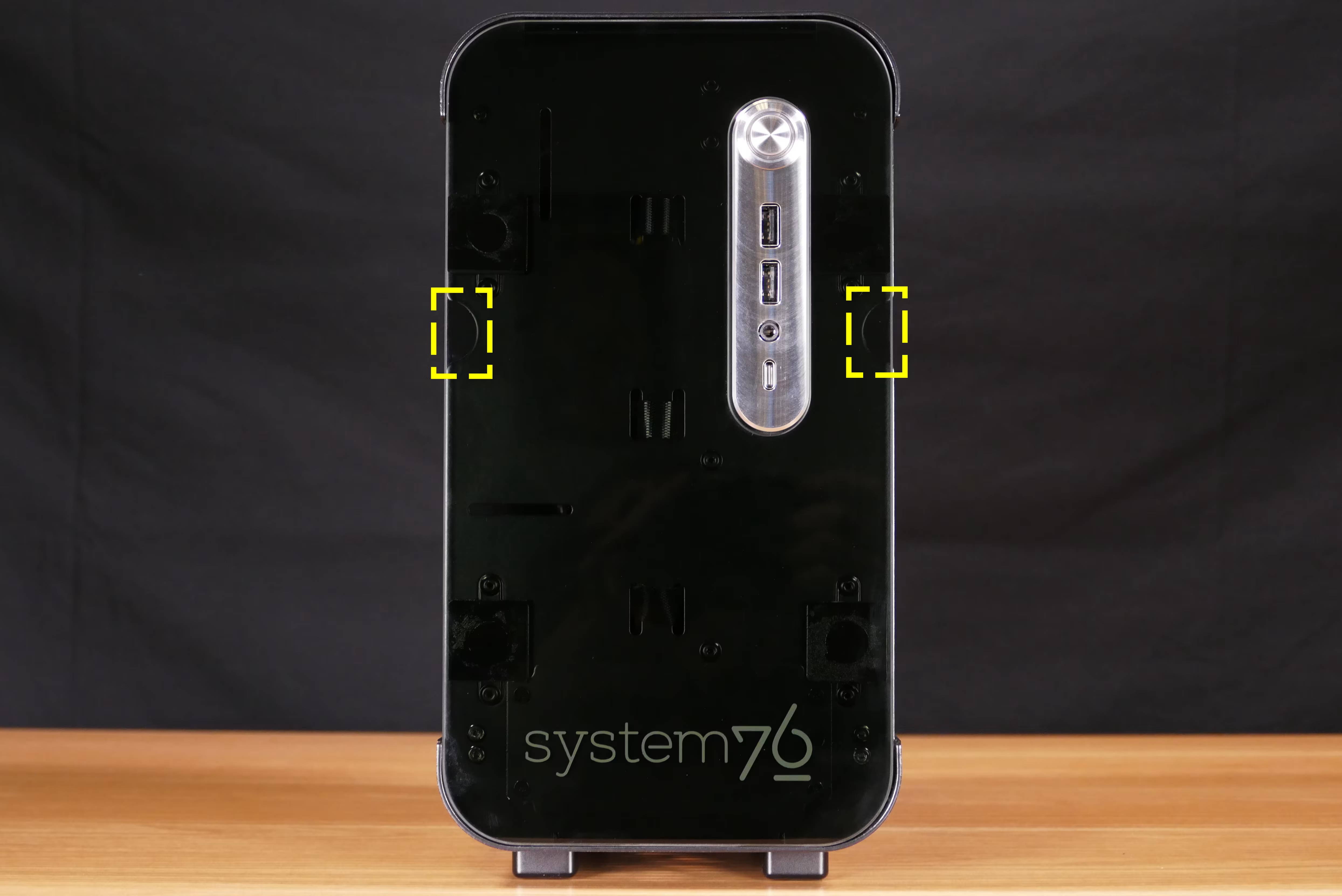
Section titled “Removing the front glass:”The front glass panel can be removed to access the screws and velcro cutouts underneath.
Tools required: Cross-head (Phillips) screwdriver (optional)
Time estimate: 3 minutes
Difficulty: Easy ●
Steps to remove the front glass:
Section titled “Steps to remove the front glass:”- Follow the steps above to remove the left and/or right side panel.
- Pull the front glass off using the front chassis cutouts.
Removing the top shell:
Section titled “Removing the top shell:”The top shell of the chassis can be removed to access the top fans.
Tools required: Cross-head (Phillips) screwdriver
Time estimate: 5 minutes
Difficulty: Easy ●
Steps to remove the top:
Section titled “Steps to remove the top:”- Follow the steps above to remove the left and right side panels and remove the front glass.
- Unscrew the four screws (two on the front, and two on the back) holding the top of the chassis on.
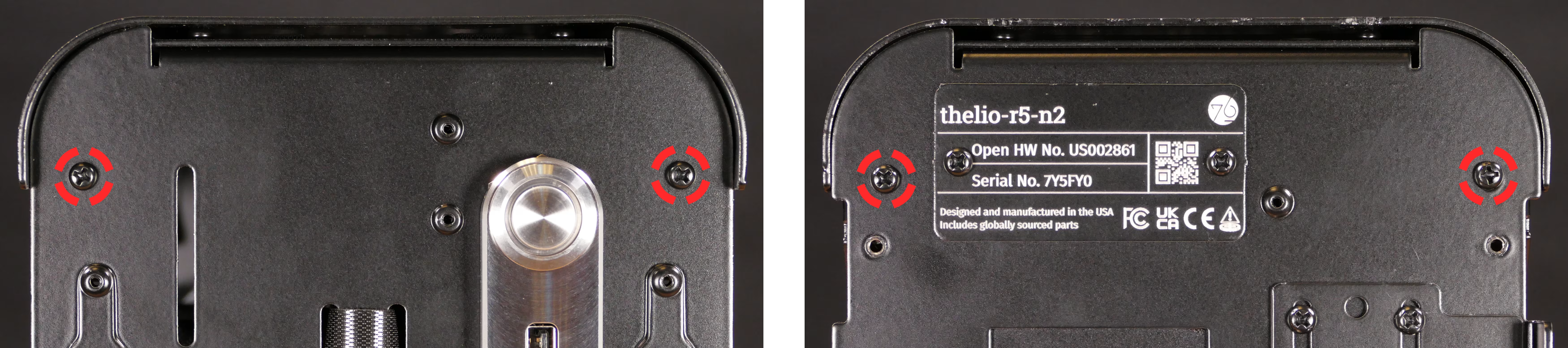
- Pull the top shell off of the chassis.
- When reinstalling the top shell, ensure the ventilation cutouts are aligned with the fans underneath; the fans are slightly farther towards the back of the chassis than the front.
Replacing the CPU fan:
Section titled “Replacing the CPU fan:”The CPU fan expels hot air from the CPU out the side of the chassis.
Part numbers:
- Id Cooling
ID12015M12S
Tools required: Cross-head (Phillips) screwdriver
Time estimate: 6 minutes
Difficulty: Easy ●
Steps to replace the CPU fan:
Section titled “Steps to replace the CPU fan:”- Follow the steps above to remove the right side panel.
- Unscrew the four CPU fan screws, highlighted yellow below.
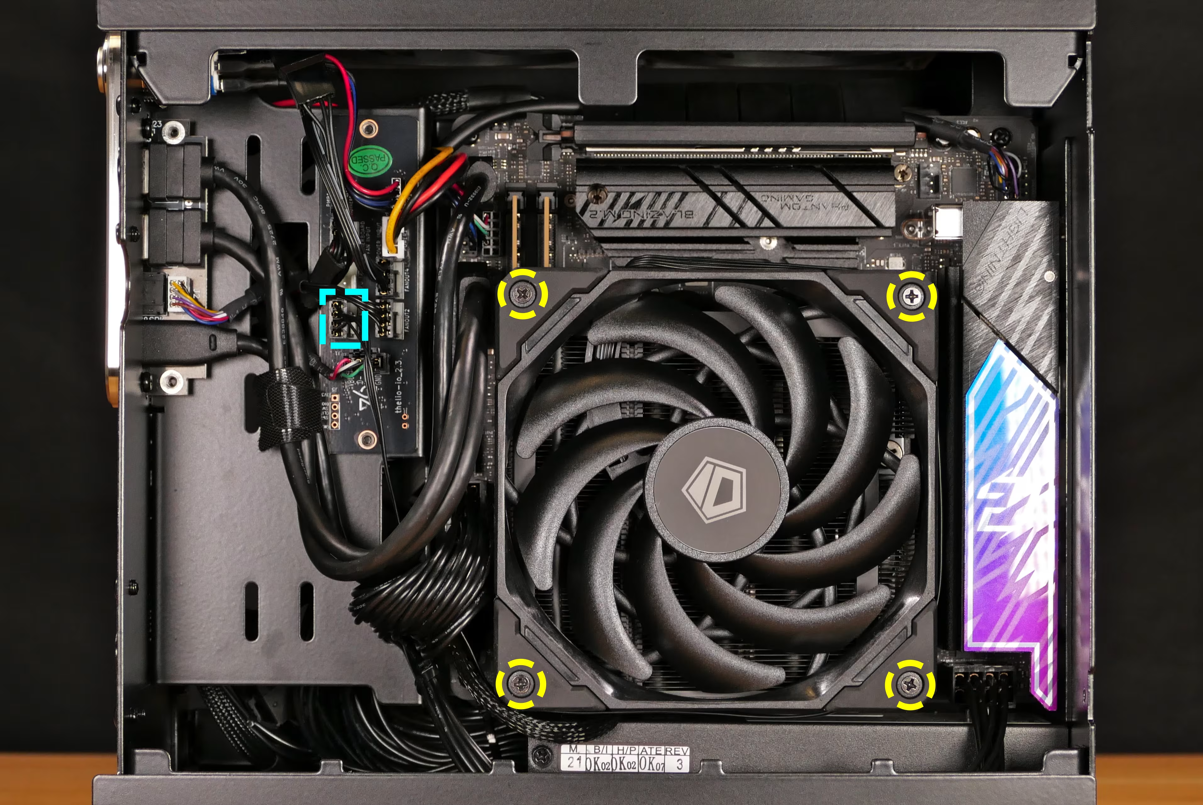
- Lower the fan away from the heatsink.
- Unplug the fan from the
FANOUT1/CPU FANheader on the Thelio Io board, highlighted cyan above.- This step can be skipped if you’re accessing components underneath the CPU cooler but are not actually replacing the CPU fan.
- Plug the new fan into the
FANOUT1/CPU FANheader (or reconnect the existing fan). - Screw the fan onto the CPU cooler heatsink.
- The spinning side of the fan faces outward, while the stationary cover faces the heatsink.
- The fan should be oriented so the cable starts at the top left of the fan, then wraps around the right side and bottom of the fan before plugging into the Thelio Io board.
Replacing the CPU heatsink & thermal paste:
Section titled “Replacing the CPU heatsink & thermal paste:”The CPU heatsink dissipates heat from the CPU to the fan. It can be removed to access components below it on the motherboard, including the RAM.
If the CPU heatsink is removed, it’s recommended to replace the thermal paste for optimal cooling performance.
Part numbers:
- Id Cooling
IS-55
Tools required: Cross-head (Phillips) screwdriver
Time estimate: 8 minutes
Difficulty: Medium ●
Steps to remove the CPU heatsink:
Section titled “Steps to remove the CPU heatsink:”- While holding the heatsink in place so it doesn’t fall, unscrew the two heatsink screws.
- The screws are held captive, and will not come away from the heatsink when fully unscrewed.
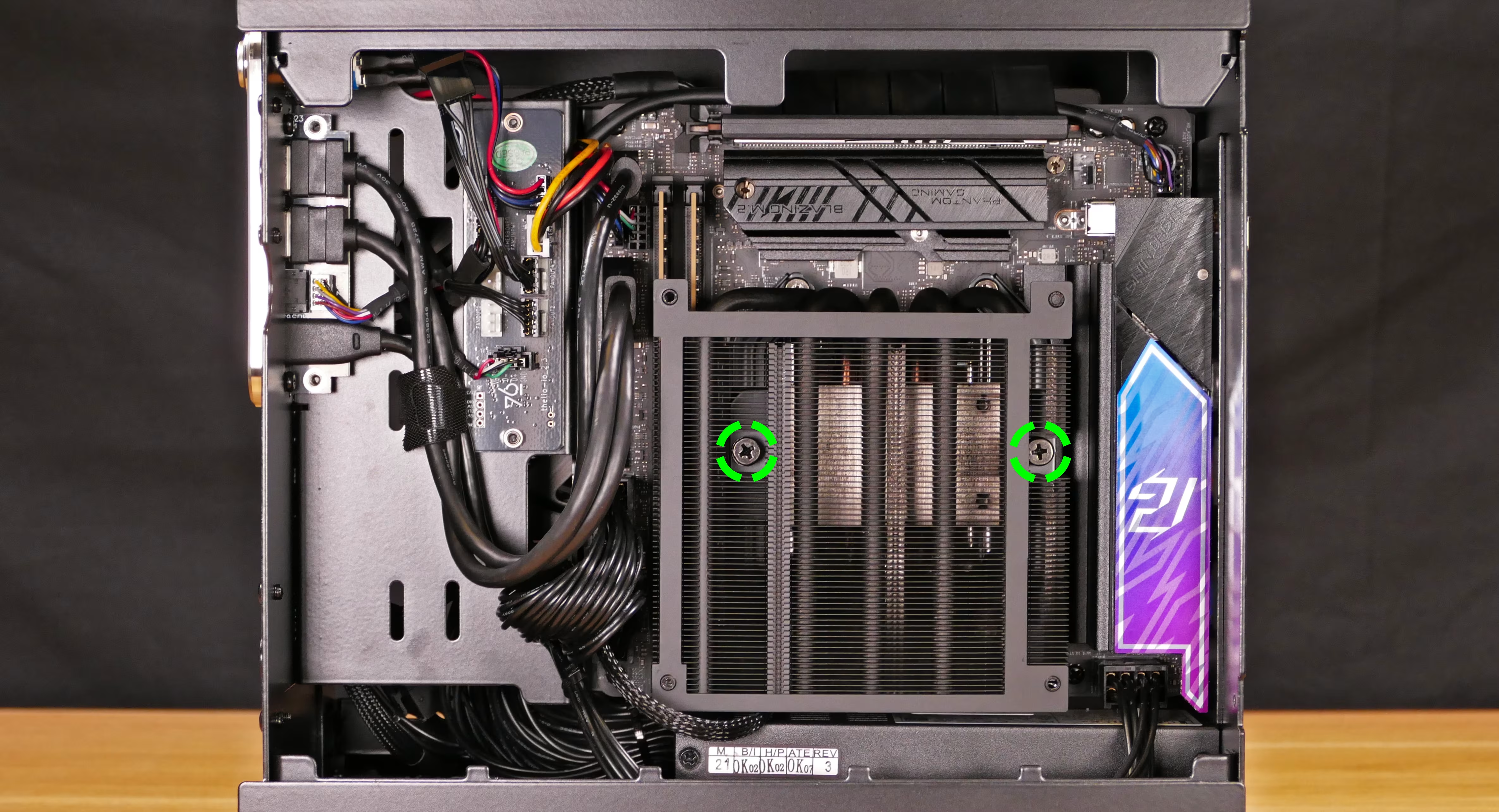
- Lower the heatsink away from the CPU.
Steps to replace the thermal paste:
Section titled “Steps to replace the thermal paste:”- Using a paper towel, clean the existing thermal paste off of the CPU and the heatsink.
- You may also use a small amount of rubbing alcohol if the old paste is dried or difficult to remove.
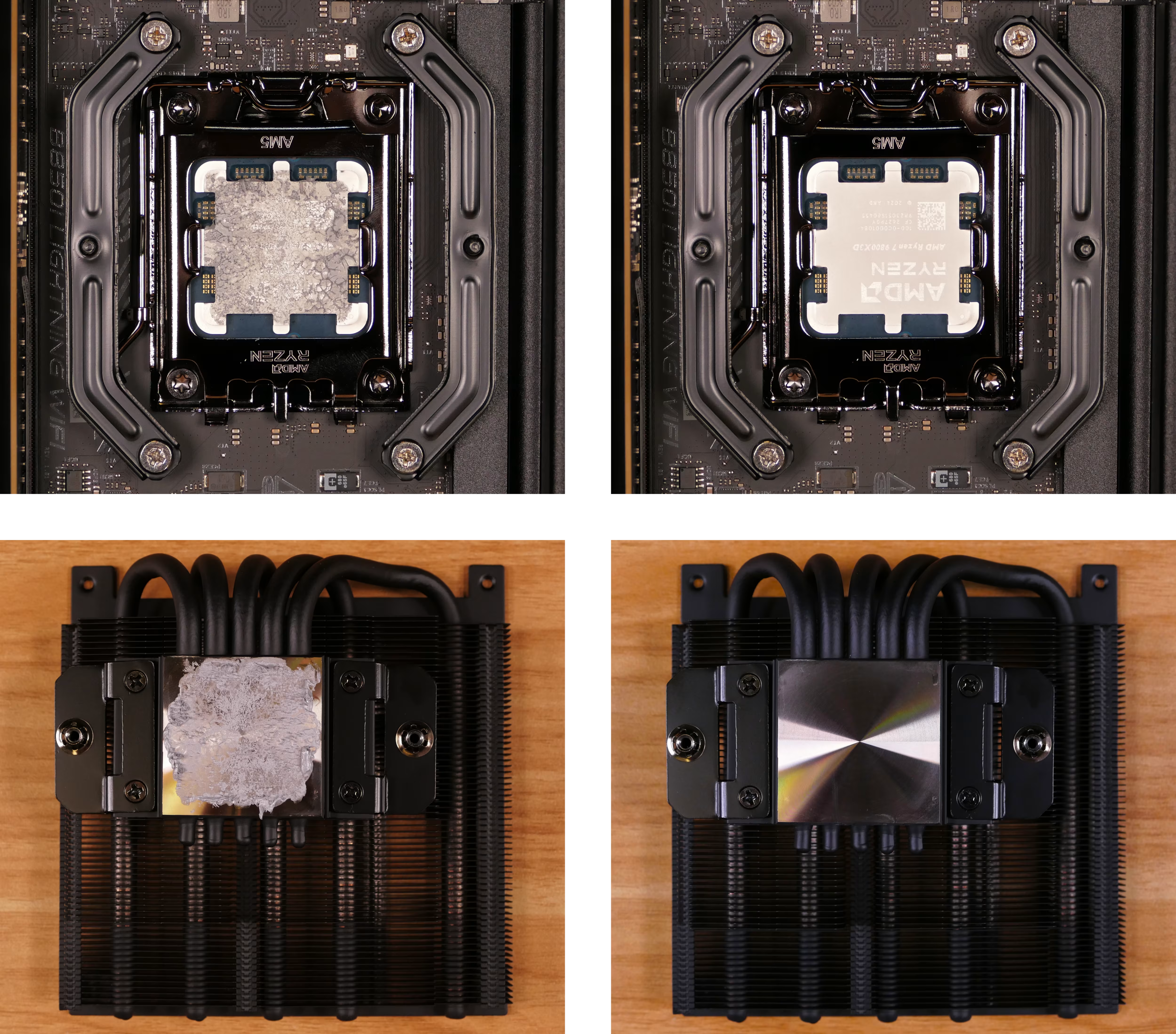
- Draw an
Xshape of thermal paste onto the CPU.
Steps to install the CPU heatsink:
Section titled “Steps to install the CPU heatsink:”- Hold the heatsink against the CPU and the mounting brackets.
- Orient the heatsink so the larger portion of fins sits below the screws.
- Partially screw each heatsink screw into the mounting brackets, then fully tighten each screw.
Replacing the RAM:
Section titled “Replacing the RAM:”Thelio Prime R5-N2 supports up to 96GB (2x48GB) of ECC DDR5 RAM running at a speed of 6400 MHz. If you’ve purchased new RAM, need to replace your RAM, or are reseating your RAM, follow these steps.
Tools required: Cross-head (Phillips) screwdriver
Time estimate: 12 minutes
Difficulty: Medium ●
Steps to replace the RAM:
Section titled “Steps to replace the RAM:”- Follow the steps above to remove the right side panel, remove the CPU fan, and remove the CPU heatsink.
- To remove an existing RAM stick, flip the bottom latch away from the stick, then pull the stick out of the slot, starting at the bottom.
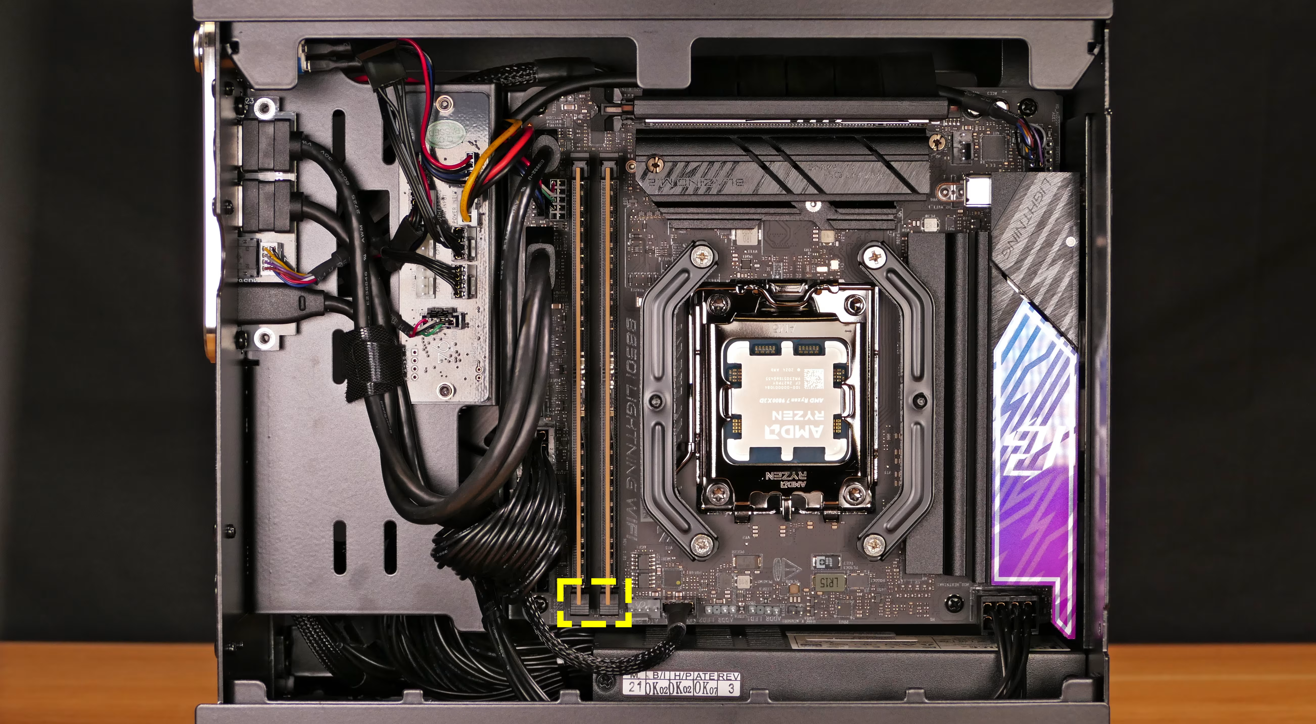
- Make sure the tab on the bottom of the slot is open (pulled away from the slot), then insert the new RAM (or re-seat the existing RAM) into the slot.
- The RAM stick will only fit in one direction. The larger group of pins goes on the bottom.
- Insert the top edge first, then push the bottom edge in until its latch clicks closed, followed by pushing the top edge until it clicks into the stationary top of the slot (or stops moving into the slot).
- If you are only using one RAM stick, place it in the left-side slot (farthest from the CPU).
- Reinstall the thermal paste, CPU heatsink, CPU fan, and right side panel.
Replacing the GPU:
Section titled “Replacing the GPU:”Thelio Prime ships with an optional dedicated GPU connected to the PCIe 5.0 x16 slot via a riser card. GPUs up to two slots tall are supported.
Tools required: Cross-head (Phillips) screwdriver
Time estimate: 8 minutes
Difficulty: Medium ●
Steps to replace the GPU:
Section titled “Steps to replace the GPU:”- Follow the steps above to remove the left side panel.
- Partially loosen the two screws holding the top PCIe bracket in place, and ensure it’s loose enough to slide into the upmost position.
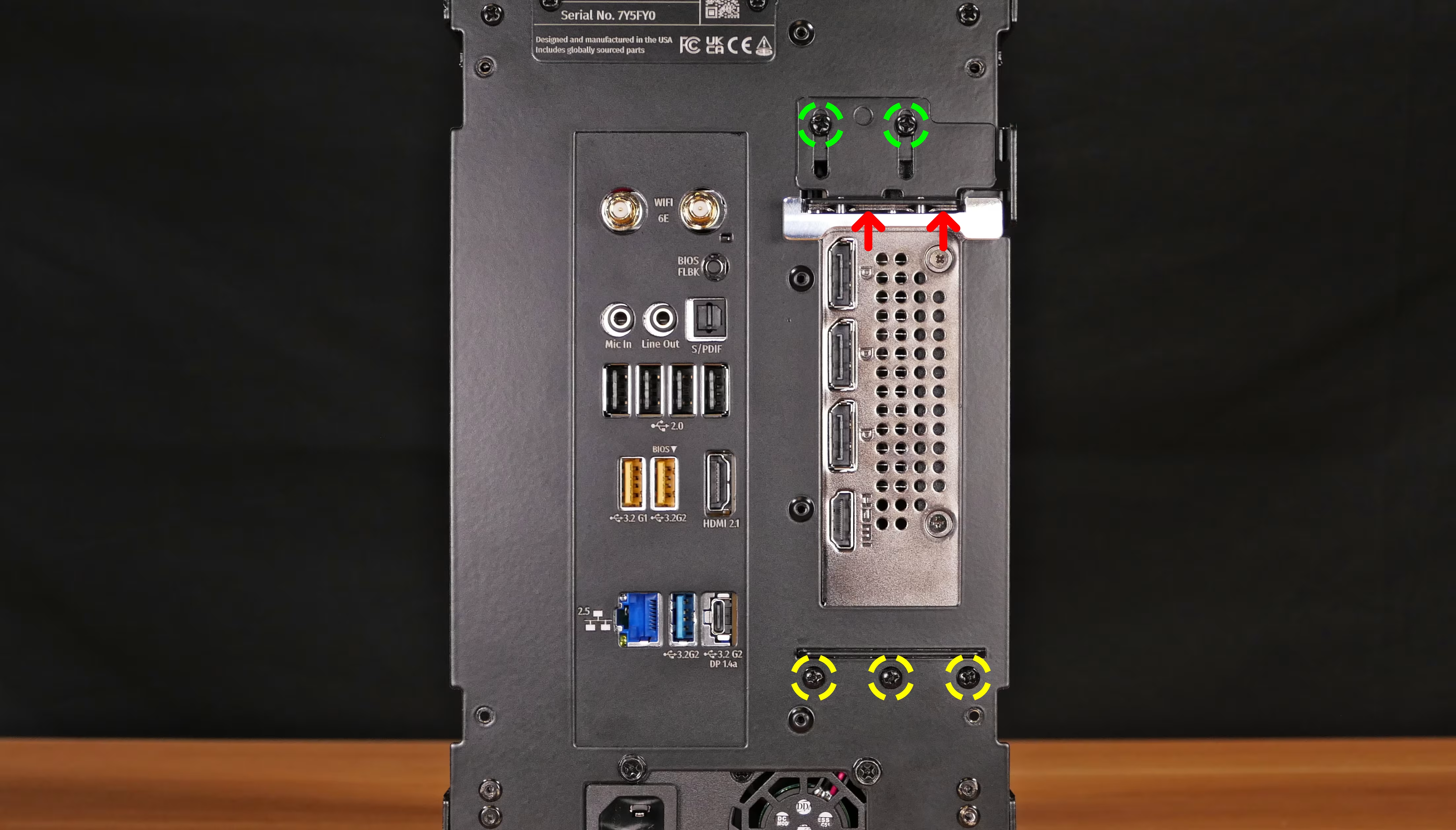
- Partially loosen the three screws holding the bottom PCIe bracket in place.
- If necessary, ensure the white PCIe latch on the riser board is opened away from the GPU.
- The riser board’s latch does not fit all PCIe cards, and may not be closed even if the GPU is inserted fully into the PCIe slot. The chassis brackets should be used as the primary indication that the GPU is inserted far enough into the riser board.
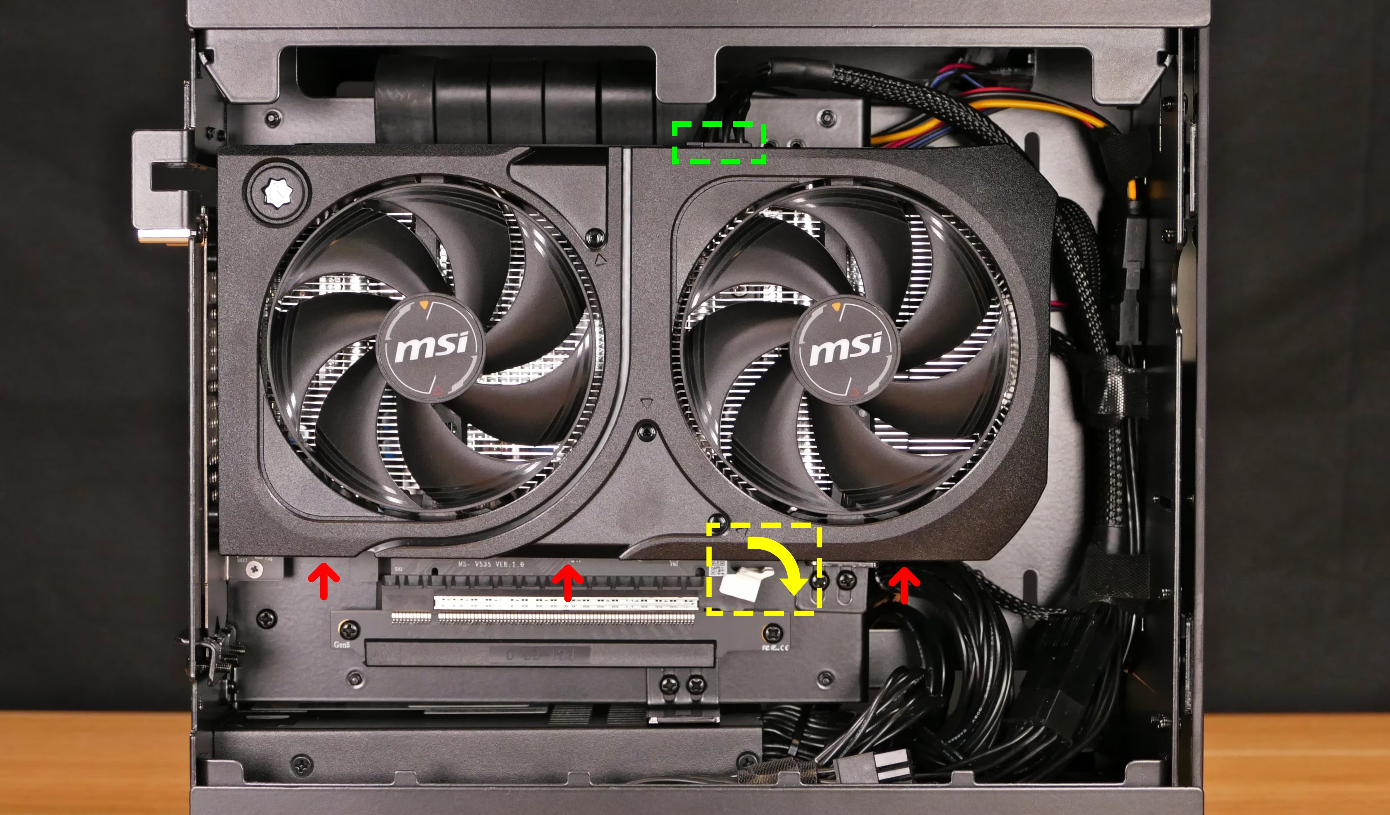
- Pull the GPU up and out of the riser slot.
- If the GPU won’t move, loosen the back PCIe brackets more, or remove them entirely.
- Unplug any power connectors from the GPU.
- Plug any necessary GPU power cables into the new GPU.
- Insert the new GPU (or re-seat the existing GPU) into the riser slot.
- It may be necessary to guide the GPU’s backplate into the bottom PCIe bracket.
- Close and tighten the back PCIe brackets, and close the slot’s PCIe latch if possible.
- Reinstall the left side panel.
Replacing the GPU riser:
Section titled “Replacing the GPU riser:”The GPU riser connects the GPU on the left side of the chassis to the PCI Express slot on the right side of the chassis. It can be removed to access components underneath or replaced if it’s damaged.
Tools required: Cross-head (Phillips) screwdriver
Time estimate: 15 minutes
Difficulty: Medium ●
Steps to replace the GPU riser:
Section titled “Steps to replace the GPU riser:”- Follow the steps above to remove both side panels and remove the dedicated GPU (if installed).
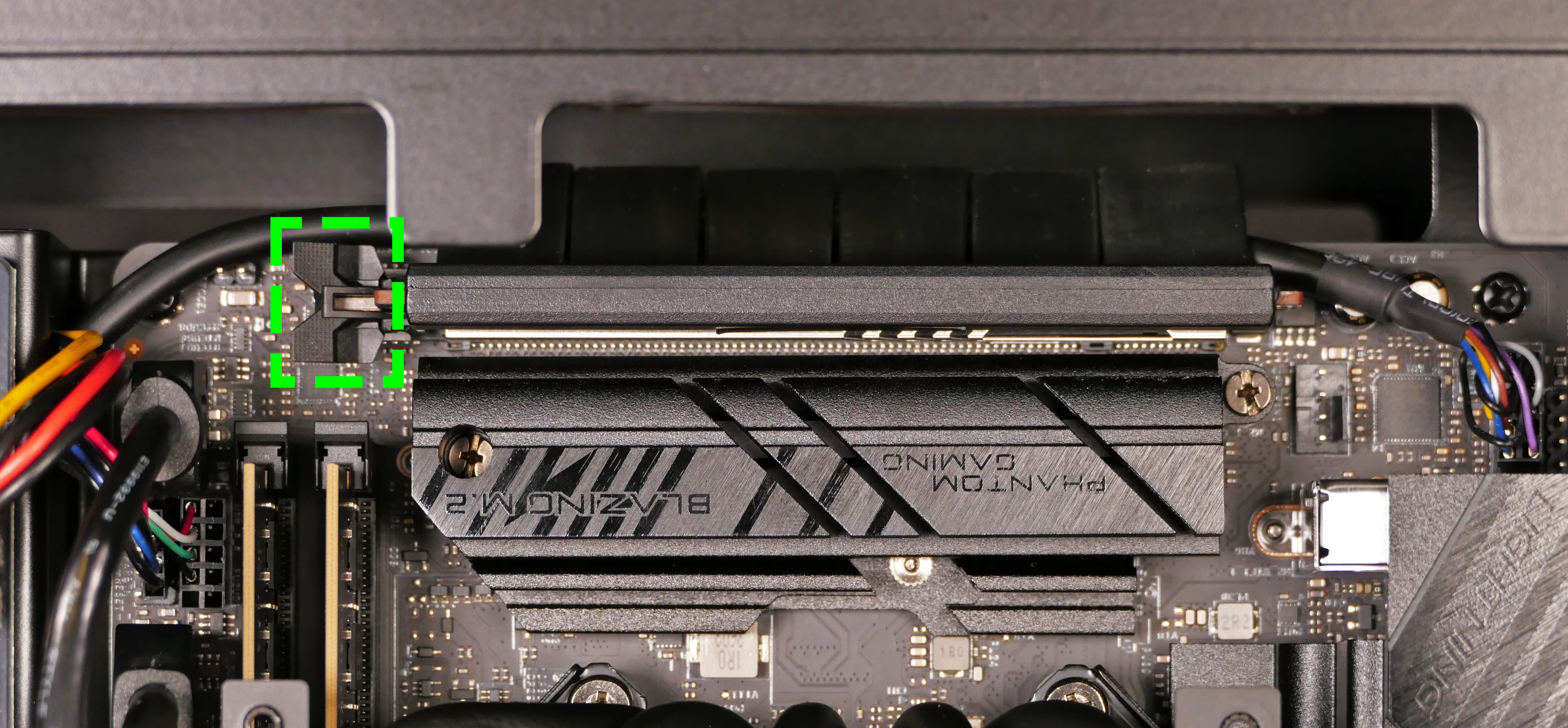
- On the right side of the machine, press the PCIe latch towards the motherboard to free the GPU riser from the PCIe slot.
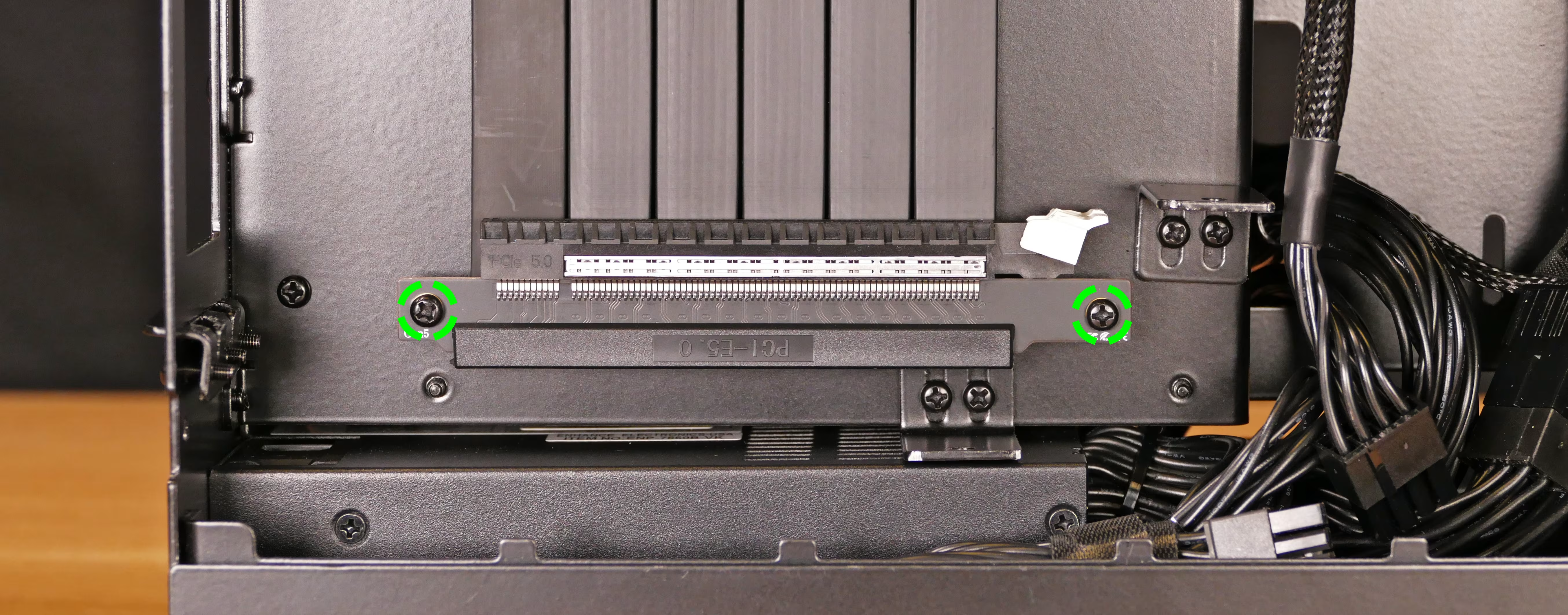
- On the left side of the machine, unscrew the two screws holding the GPU riser onto the chassis.
- Once both sides have been freed, feed one end of the GPU riser through the top cutout in the chassis.
- It’s easiest to slide the male end of the riser through in the same orientation as it would plug into the motherboard’s PCIe slot.
- Remove and replace the GPU riser.
- Screw the new GPU riser into place.
- Feed the new GPU riser’s male end through the top cutout in the chassis.
- Plug the GPU riser into the motherboard’s PCIe slot, pressing both sides of the riser connector into the slot until the PCIe latch shuts.
- Reinstall the GPU (if applicable) and side panels.
Replacing the M.2 drives:
Section titled “Replacing the M.2 drives:”Thelio Prime R5-N2 has two M.2 storage slots. Both slots are M-key and size 2280. Slot 1 (above the CPU) supports PCIe NVMe Gen 5, while Slot 2 (on the back of the motherboard) supports PCIe NVMe Gen 4.
Tools required: Cross-head (Phillips) screwdriver
Time estimate: 15 minutes
Difficulty: Easy ●
Steps to replace the M.2 drive (Slot 1):
Section titled “Steps to replace the M.2 drive (Slot 1):”- Follow the steps above to remove the right side panel.
- While holding the M.2 heatsink so it doesn’t fall, unscrew the two screws holding the M.2 heatsink onto the motherboard.
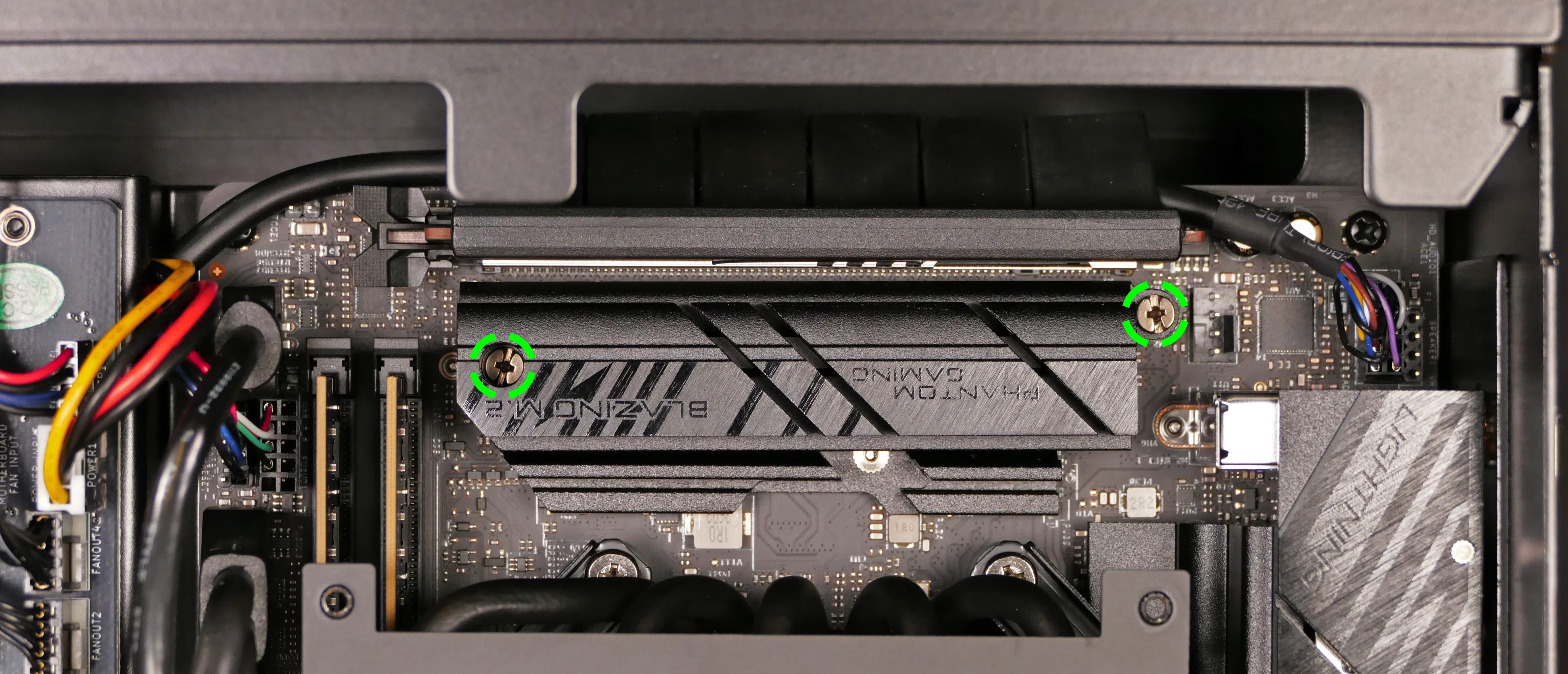
- Pull the M.2 heatsink away from the motherboard. The M.2 drive will pop away from the motherboard at an angle.
- Pull the M.2 drive out of the slot.
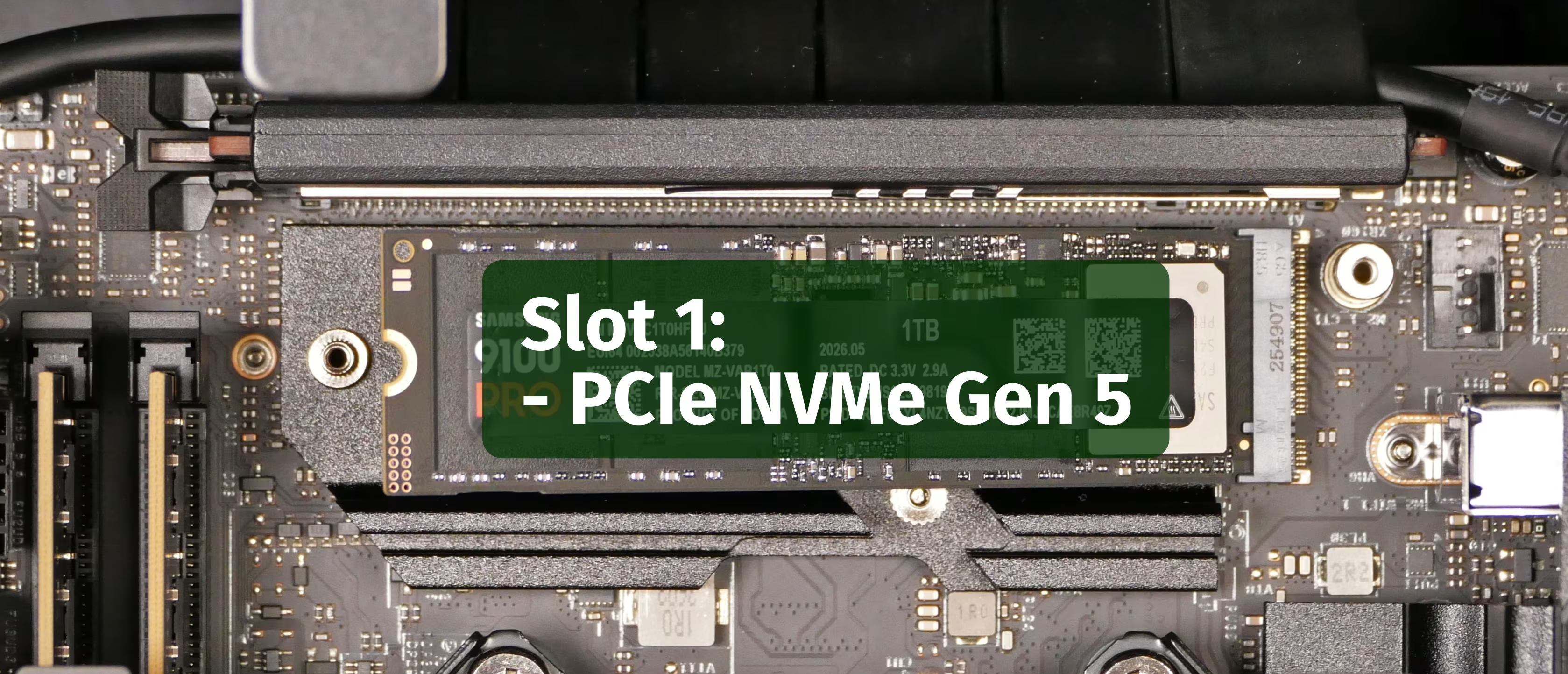
- Insert the new M.2 drive (or reinstall the existing M.2 drive) into the M.2 slot at a 30-degree angle.
- Reinstall the M.2 heatsink.
- Reinstall right side panel.
Steps to replace the M.2 drive (Slot 2):
Section titled “Steps to replace the M.2 drive (Slot 2):”- Follow the steps above to remove the left side panel and remove the dedicated GPU (if installed).
- You can optionally unscrew the GPU riser for easier access to the M.2 slot.
- Unscrew the retainer screw opposite the M.2 slot. The M.2 drive will pop away from the motherboard at an angle.
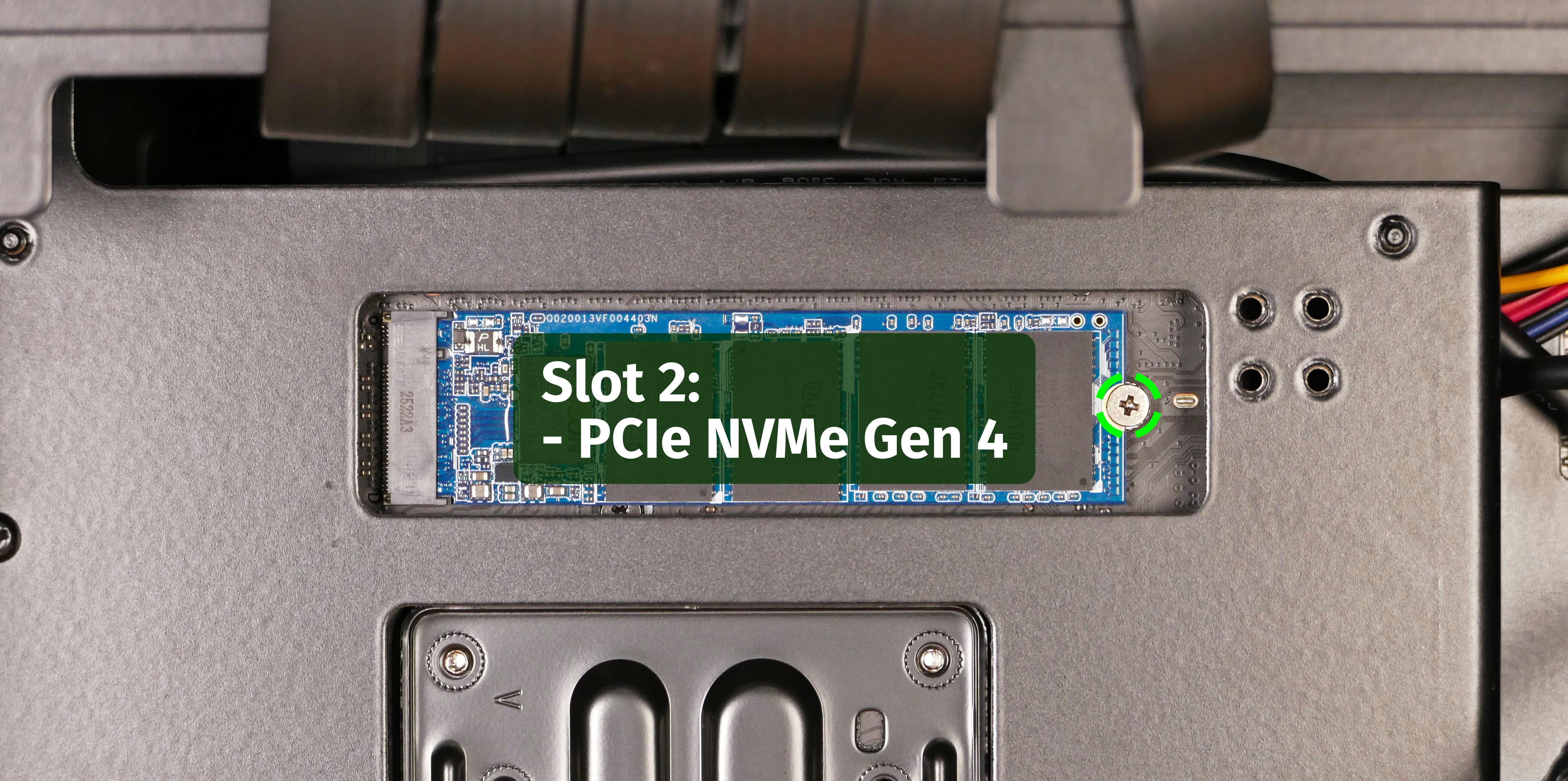
- Pull the M.2 drive out of the slot.
- Insert the new M.2 drive (or reinstall the existing M.2 drive) into the M.2 slot at a 30-degree angle.
- While holding the M.2 drive against the motherboard, reinstall the M.2 retainer screw.
- Reinstall the GPU riser, GPU, and left side panel as applicable.
Work in Progress
Section titled “Work in Progress”This repairs page is still in-progress. Please check back later for further instructions, or contact System76 support with specific questions.