

Lemur Pro (Parts & Repairs)
Many components in your Lemur Pro can be upgraded or replaced as necessary. Follow these step-by-step guides for instructions.
This page contains photos and part numbers for both the 14” model (lemp14) and the 16” model (lemp14-b). Unless otherwise noted, photos are of the 14” model (lemp14), and general component locations are the same between both models.
Removing the bottom cover:
Section titled “Removing the bottom cover:”Removing the cover is required to access the internal components. Prior to removing the cover, ensure the AC power is unplugged and all peripherals (including SD cards and USB drives) are unplugged or removed from the system.
Part numbers:
- 14” bottom panel:
6-39-L24J3-012 - 16” bottom panel:
6-39-L26J3-012 - Replacement product model stickers can be obtained from System76 support.
Tools required: Cross-head (Phillips) screwdriver, plastic spudger tool (optional)
Time estimate: 5 minutes
Difficulty: Easy ●
Steps to remove the bottom cover:
Section titled “Steps to remove the bottom cover:”- Place the machine lid-side down.
- Use a soft surface (such as a towel) to avoid scratches.
- Remove the screws from the bottom panel.
- The 14” model (lemp14) has 12 screws.
- The 16” model (lemp14-b) has 11 screws.
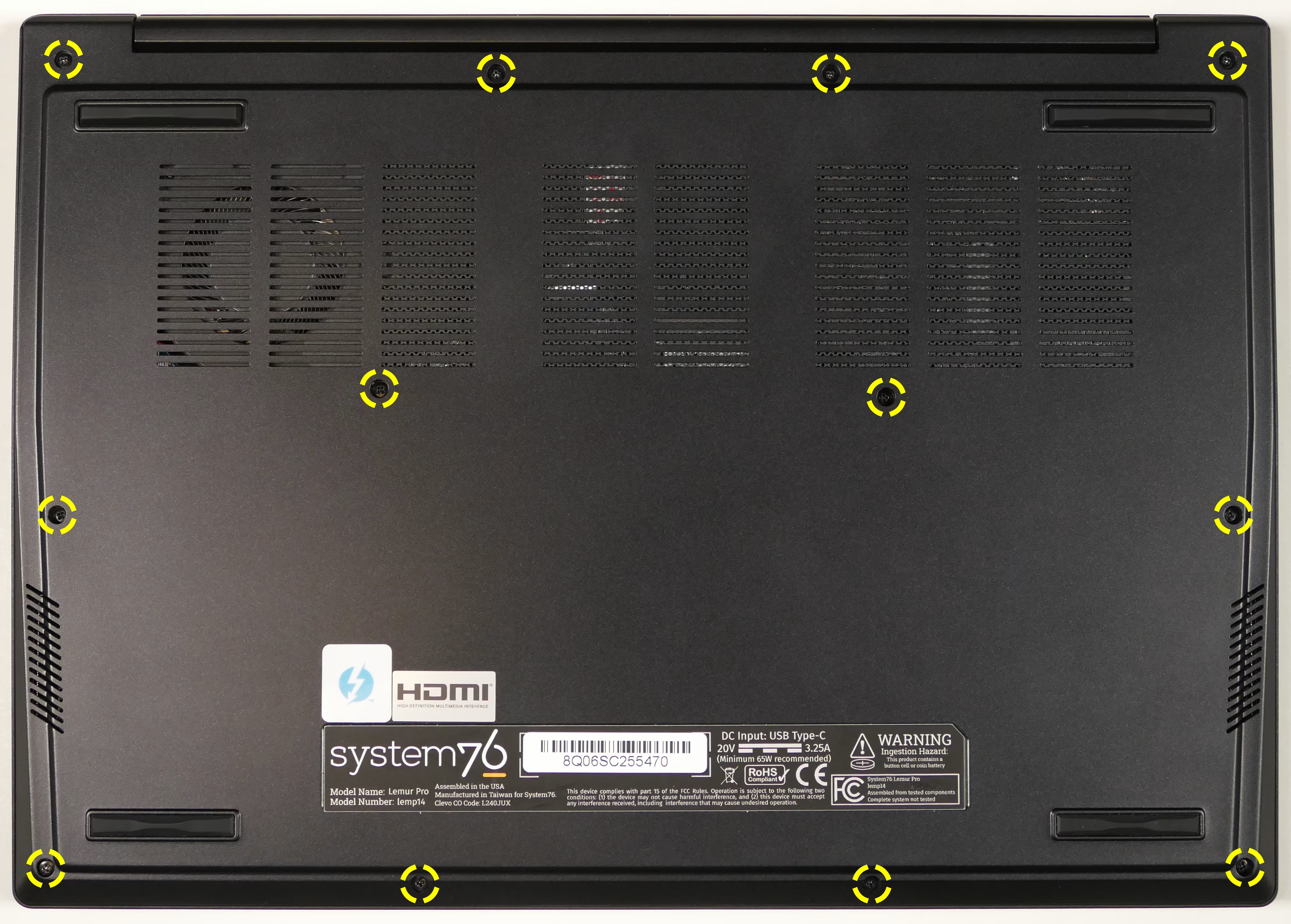
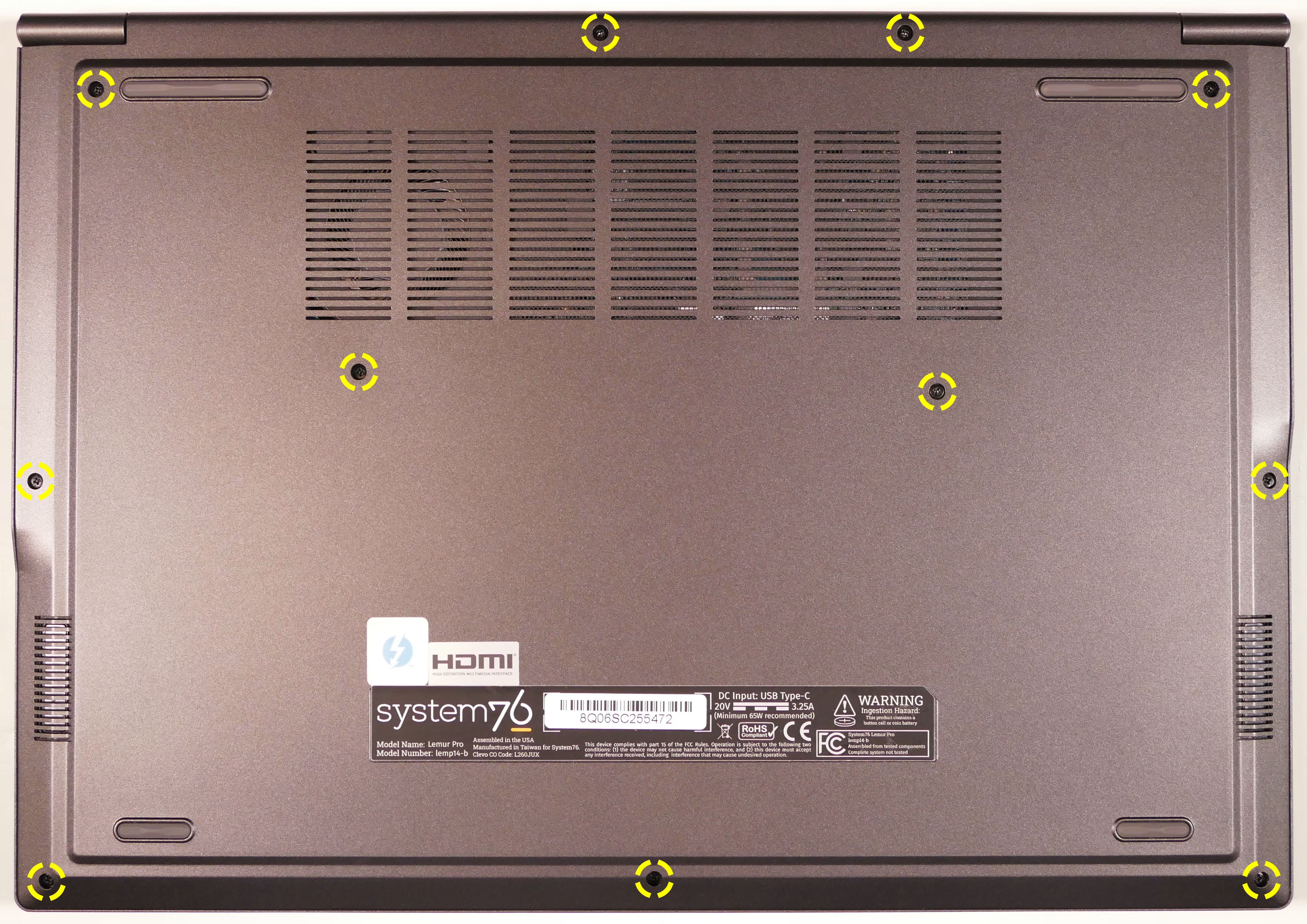
- Lift the bottom cover off, starting from the hinges in the back.
- For the 16” model (lemp14-b), a plastic spudger tool may be necessary to help grip and pry the cover off. After starting at the hinges, work the spudger forward along the sides of the chassis until the cover fully separates.
Replacing an M.2/NVMe SSD:
Section titled “Replacing an M.2/NVMe SSD:”The Lemur Pro 14 supports one M.2 SSD. The slot is size 2280, and the connector uses PCIe NVMe Generation 4.
Tools required: Cross-head (Phillips) screwdriver
Time estimate: 10 minutes
Difficulty: Easy ●
Steps to replace the M.2 drive:
Section titled “Steps to replace the M.2 drive:”- Follow the steps above to remove the bottom cover.
- Unscrew the retainer screw opposite the M.2 slot.
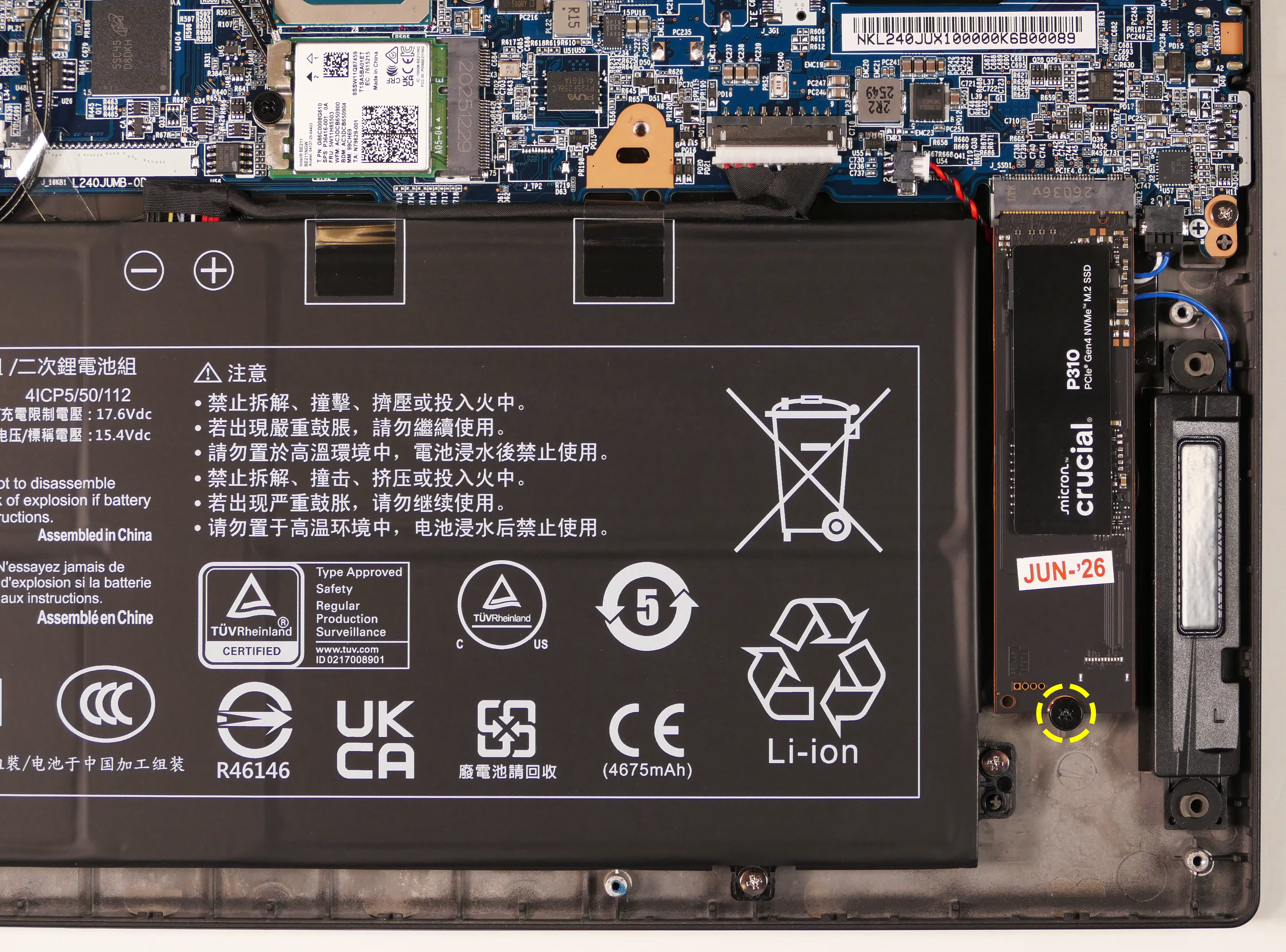
- Remove the existing M.2 drive by pulling it out of the slot.
- Insert the new M.2 drive into the slot and hold it down.
- Replace the retainer screw.
Replacing the wireless card:
Section titled “Replacing the wireless card:”Your system’s WiFi and Bluetooth are both handled by the same module. It connects with a standard M.2 2230 slot with PCIe and USB interfaces (E-key).
Part numbers:
- The standard wireless card is an Intel
BE211NGW.
Tools required: Cross-head (Phillips) screwdriver
Time estimate: 10 minutes
Difficulty: Medium ●
Steps to replace the WiFi/Bluetooth module:
Section titled “Steps to replace the WiFi/Bluetooth module:”- Follow the steps above to remove the bottom cover.
- Unscrew the wireless card screw holding the card and its wire bracket in place.
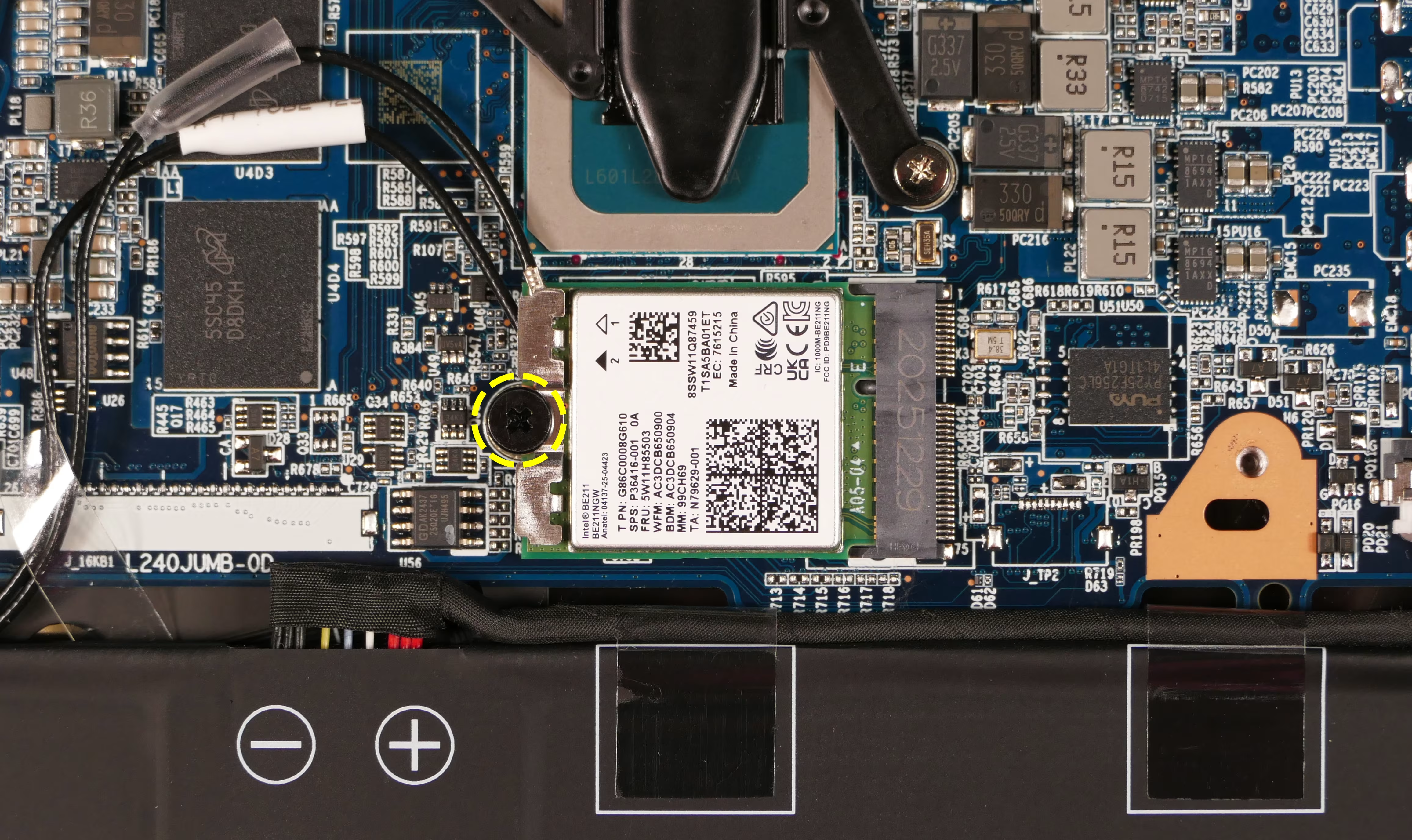
- Remove the metal bracket that holds the wires onto the card.
- Gently remove the two antennas (highlighted red below) by pulling them up and away from the wireless card.
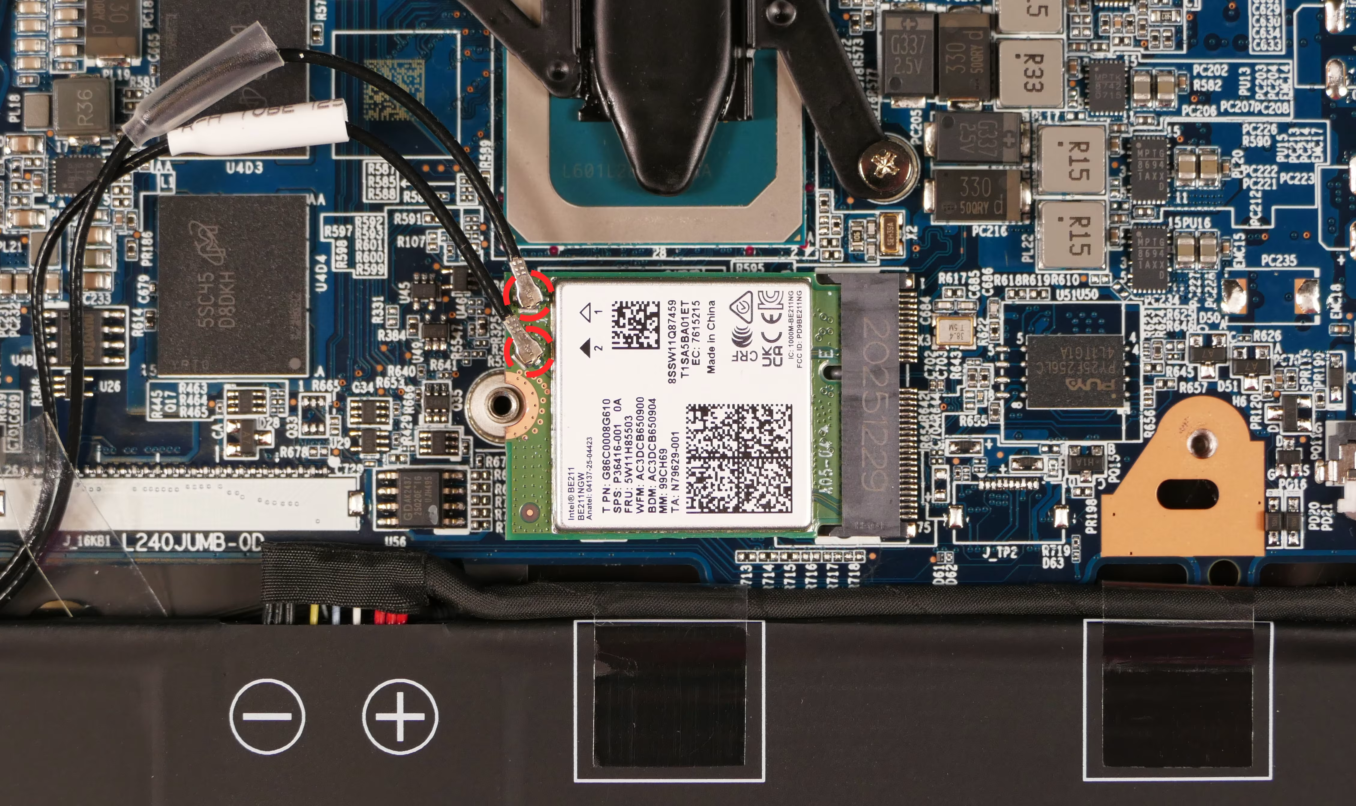
- The wireless card will pop up at an angle. Remove the card from the M.2 slot.
- Insert the new wireless card into the M.2 slot at an angle.
- While holding the card down against the screw hole, attach the two antennas by aligning the circular fittings and pressing onto the wireless card. The connectors will snap into place.
- Use caution when attaching the connectors; the pins can bend, break, or snap.
- Reinstall the metal bracket and the retaining screw.
- Reinstall the bottom panel.
Replacing the main battery:
Section titled “Replacing the main battery:”The battery provides primary power whenever the system is unplugged.
Part numbers:
- The battery’s model number is
L240BAT-4-73, and the original part number is6-87-L240S-74B02.- Third-party battery sellers may list one or both of these numbers, and may offer other compatible part numbers with the same model number.
- You can also contact System76 to purchase a replacement battery.
Tools required: Cross-head (Phillips) screwdriver
Time estimate: 10 minutes
Difficulty: Easy ●
Steps to replace the main battery:
Section titled “Steps to replace the main battery:”- Follow the steps above to remove the bottom cover.
- Remove the four silver battery screws along the perimeter of the battery.
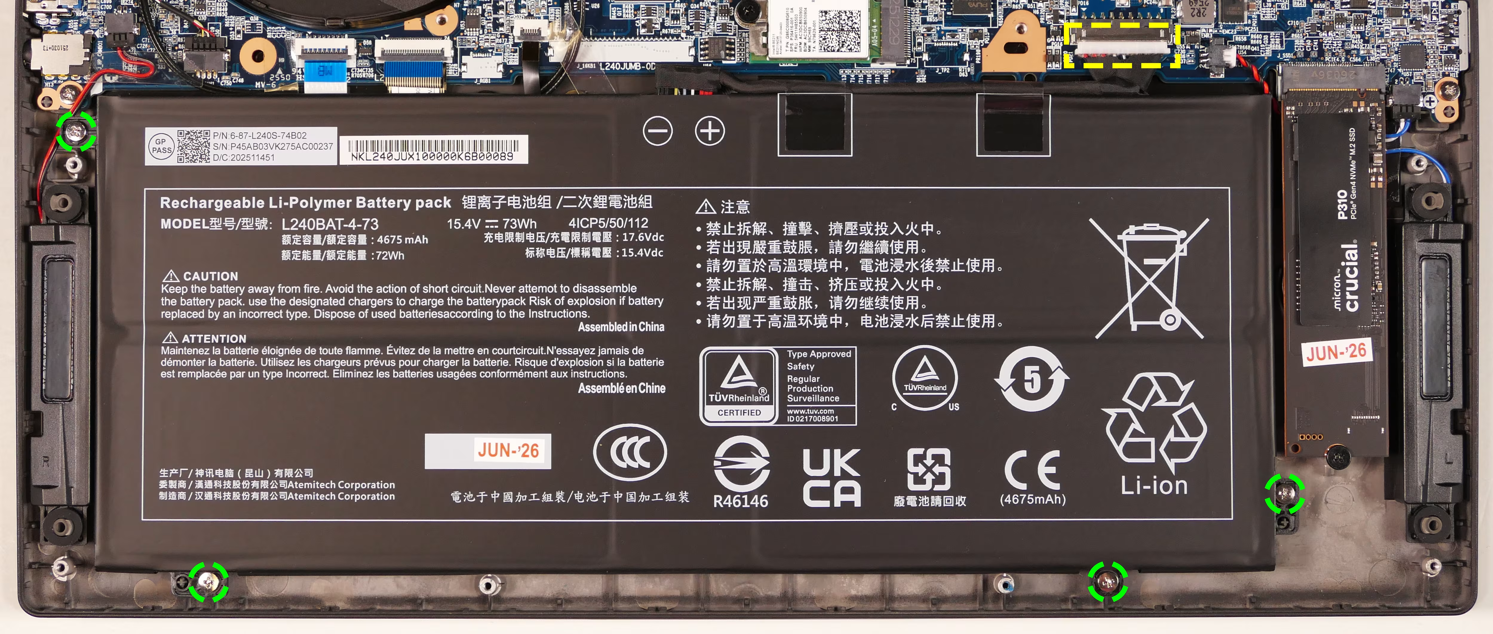
- Unplug the white connector that connects the battery to the motherboard.
- Remove the battery.
- Place the new battery into the chassis, plug in the white connector, and reinstall the four silver battery screws.
- When connecting the battery, the red wire goes on the left.
- Reinstall the bottom cover.
Replacing the CMOS battery:
Section titled “Replacing the CMOS battery:”The CMOS battery supplies power to the system’s CMOS chip. UEFI settings and the computer’s hardware clock are stored on the CMOS. If your system doesn’t boot, you can reset the CMOS to force a low-level hardware reset. If your clock is constantly resetting, it’s likely your CMOS battery needs to be replaced.
Warning (ingestion hazard): Keep batteries out of reach of children. Death or serious injury can occur if ingested. If a battery is suspected to be swallowed or inserted inside any part of the body, seek immediate medical attention. In the US, you can also call the National Battery Ingestion Hotline for guidance: +1 (800) 498-8666
Part numbers:
- The CMOS battery is a standard 3V KTS CR2032W battery.
Tools required: Cross-head (Phillips) screwdriver
Time estimate: 15 minutes
Difficulty: Medium ●
Steps to replace the CMOS battery:
Section titled “Steps to replace the CMOS battery:”- Follow the steps above to remove the bottom cover.
- Follow the steps above to remove the M.2 SSD, if installed.
- Remove any clear tape that is securing the battery, then pull the battery away from the adhesive holding it to the case.
- If you are only clearing the CMOS and are not replacing the CMOS battery, removing the SSD and CMOS battery is optional, but will make it easier to unplug the CMOS battery connector.
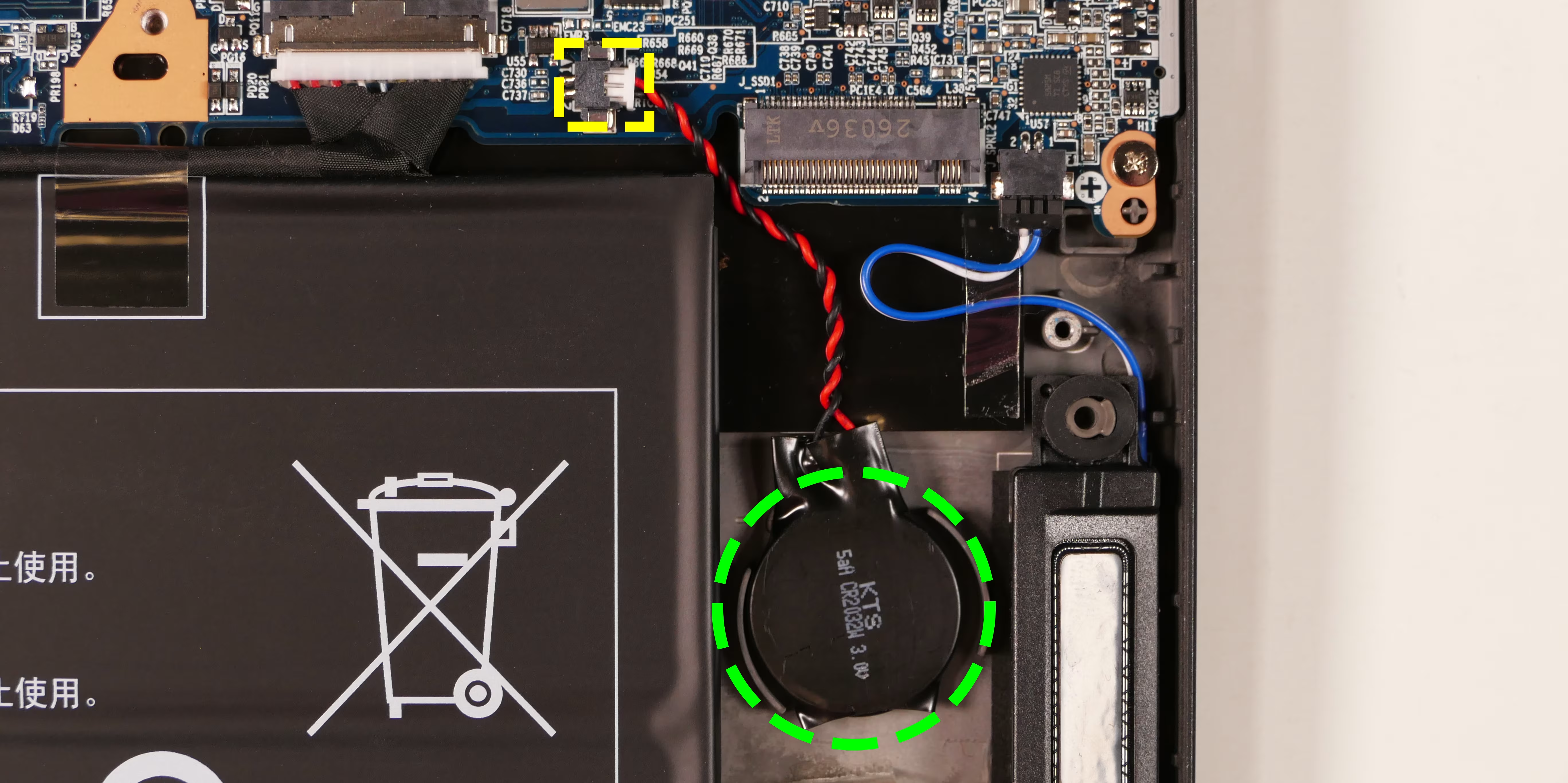
- Unplug the white connector attaching the CMOS battery to the motherboard.
- To clear the CMOS, disconnect the main battery, open the lid of the machine, and hold down the power button for at least 15 seconds to discharge any residual energy in the system.
- Re-connect the CMOS battery and the main battery, and replace the SSD and bottom panel.
- Power up the machine. The system may power itself off and on after initial boot; this is normal behavior when the CMOS has been reset.
Replacing the cooling system:
Section titled “Replacing the cooling system:”If the CPU fan becomes noisy and cleaning it out doesn’t fix the issue, you may need a new CPU fan. Contact support to start a warranty claim or parts purchase.
Depending on your climate and the age of the machine, it may be necessary to apply new thermal paste between the CPU and the heatsink. Thermal paste helps facilitate effective heat transfer between the CPU and the cooling equipment. These instructions can also be used in the unlikely event your heatsink needs to be replaced.
Part numbers:
- The fan/heatsink assembly’s part number is
6-31-L24JN-101. - The fan is an FCN
F25211 DFS5L22H15B85P EP.- The fan/heatsink is produced as a single assembly. Sourcing a replacement fan without the heatsink may not be possible.
Tools required: Cross-head (Phillips) screwdriver
Time estimate: 20 minutes
Difficulty: High ●
Steps to replace the fans/heatsink/thermal paste:
Section titled “Steps to replace the fans/heatsink/thermal paste:”- Follow the steps above to remove the bottom cover.
- Disconnect the small connector plugging the fan into the motherboard, highlighted yellow below.
- This can alternatively be done after the fan/heatsink is removed.
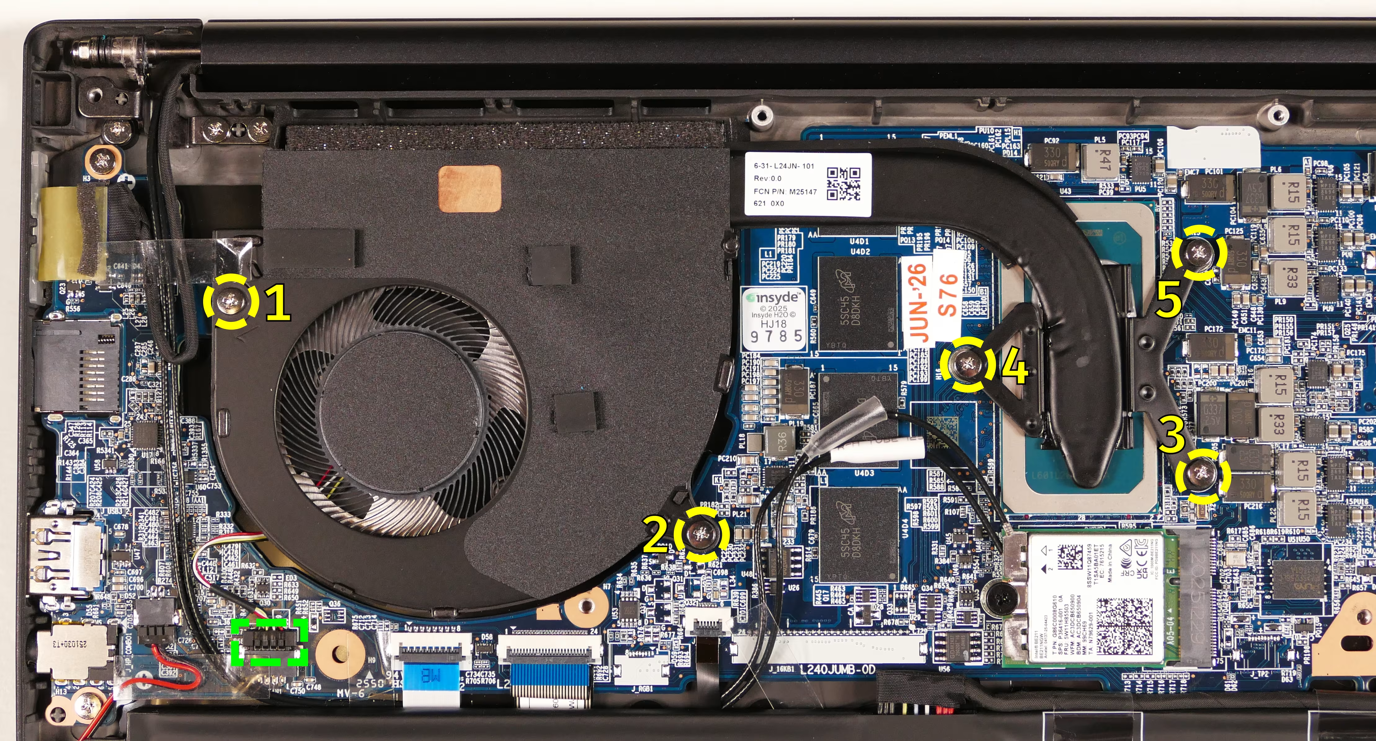
- Peel back any clear tape touching the fan’s casing.
- Remove the silver fan and heatsink screws in the order of the stamped numbers, starting with #1, then #2, and continuing until #5.
- Remove the heatsink/fan from the system, being careful not to bend the heatsink pipe. It may take some pressure to break the seal of the thermal paste.
- Using a paper towel, remove the existing thermal paste. You may also use a small amount of rubbing alcohol to remove excess or difficult-to-remove paste.
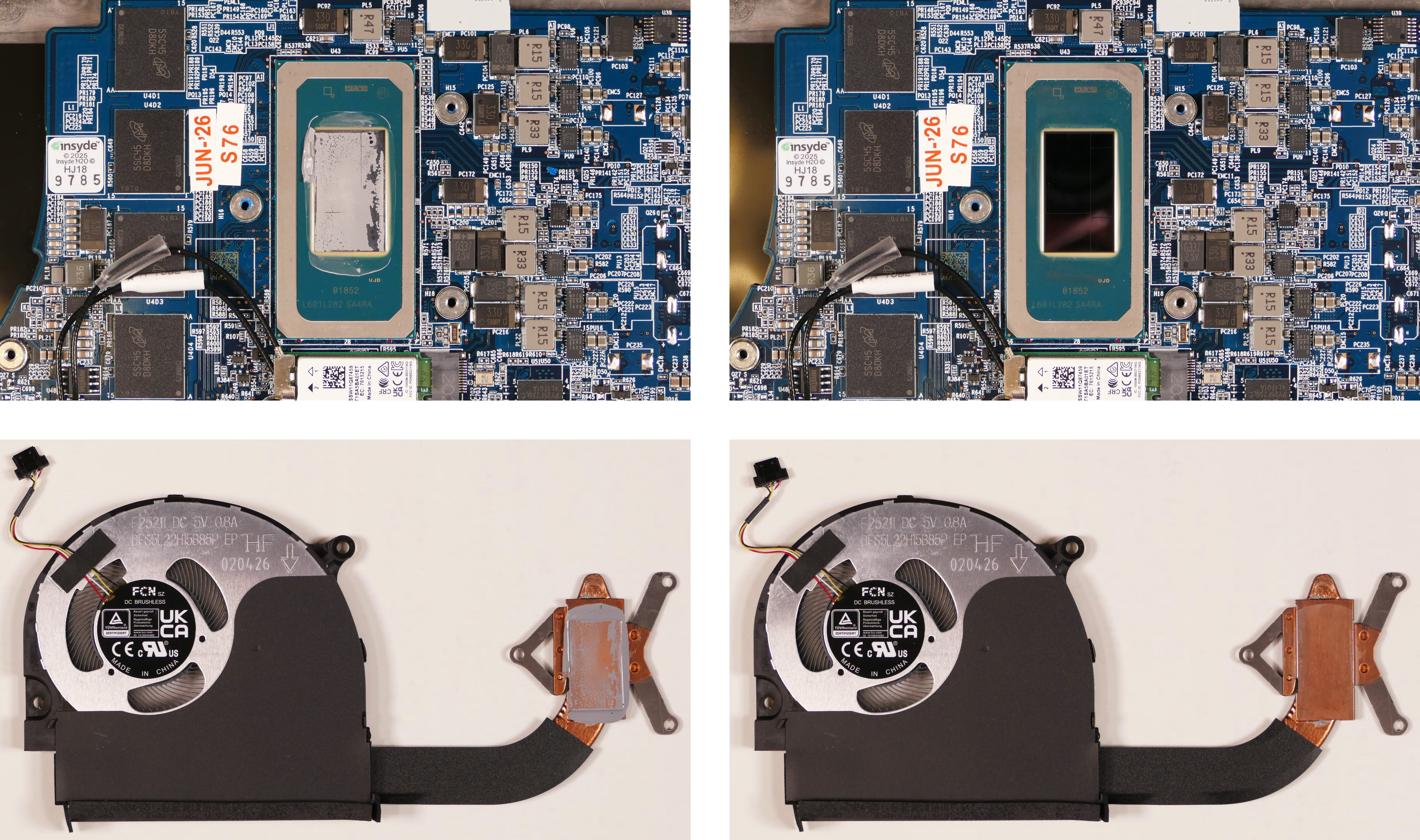
- After cleaning the CPU and heatsink, apply a small line of thermal paste directly onto the CPU.
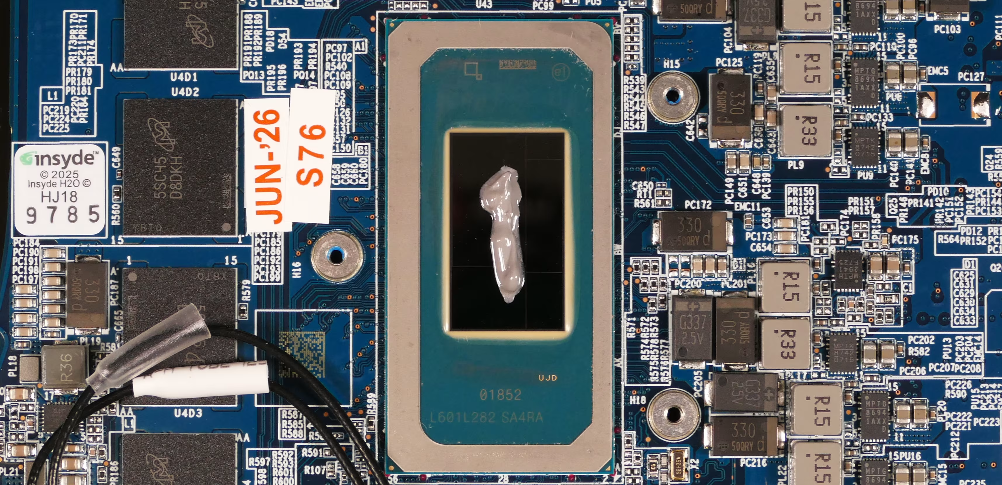
- Carefully replace the fan and heatsink.
- Replace the fan and heatsink screws in the order of the stamped numbers, starting with #1, then #2, and continuing until #5.
- Plug the fan back in.
- When plugging the fan in, the black wire goes on the left (closest to the side of the machine.)
Replacing the speakers:
Section titled “Replacing the speakers:”The system has two bottom-firing speakers, which can be removed and replaced individually.
Part numbers:
- 14” model (lemp14):
- The left speaker’s model number is
L240TU-L-BASS, and its part number is6-23-5L240-0L2. - The right speaker’s model number is
L240TU-R-BASS, and its part number is6-23-5L240-0R2.
- The left speaker’s model number is
- 16” model (lemp14-b):
- The left speaker’s model number is
L260TU-L-BASS, and its part number is6-23-5L260-0L2. - The right speaker’s model number is
L260TU-R-BASS, and its part number is6-23-5L260-0R2.
- The left speaker’s model number is
Tools required: Cross-head (Phillips) screwdriver
Time estimate: 15 minutes
Difficulty: Easy ●
Steps to replace the speakers:
Section titled “Steps to replace the speakers:”- Follow the steps above to remove the bottom cover.
- In the below photo, the M.2 SSD has also been removed for greater visibility.
- Pull the speaker(s) off of the plastic posts.
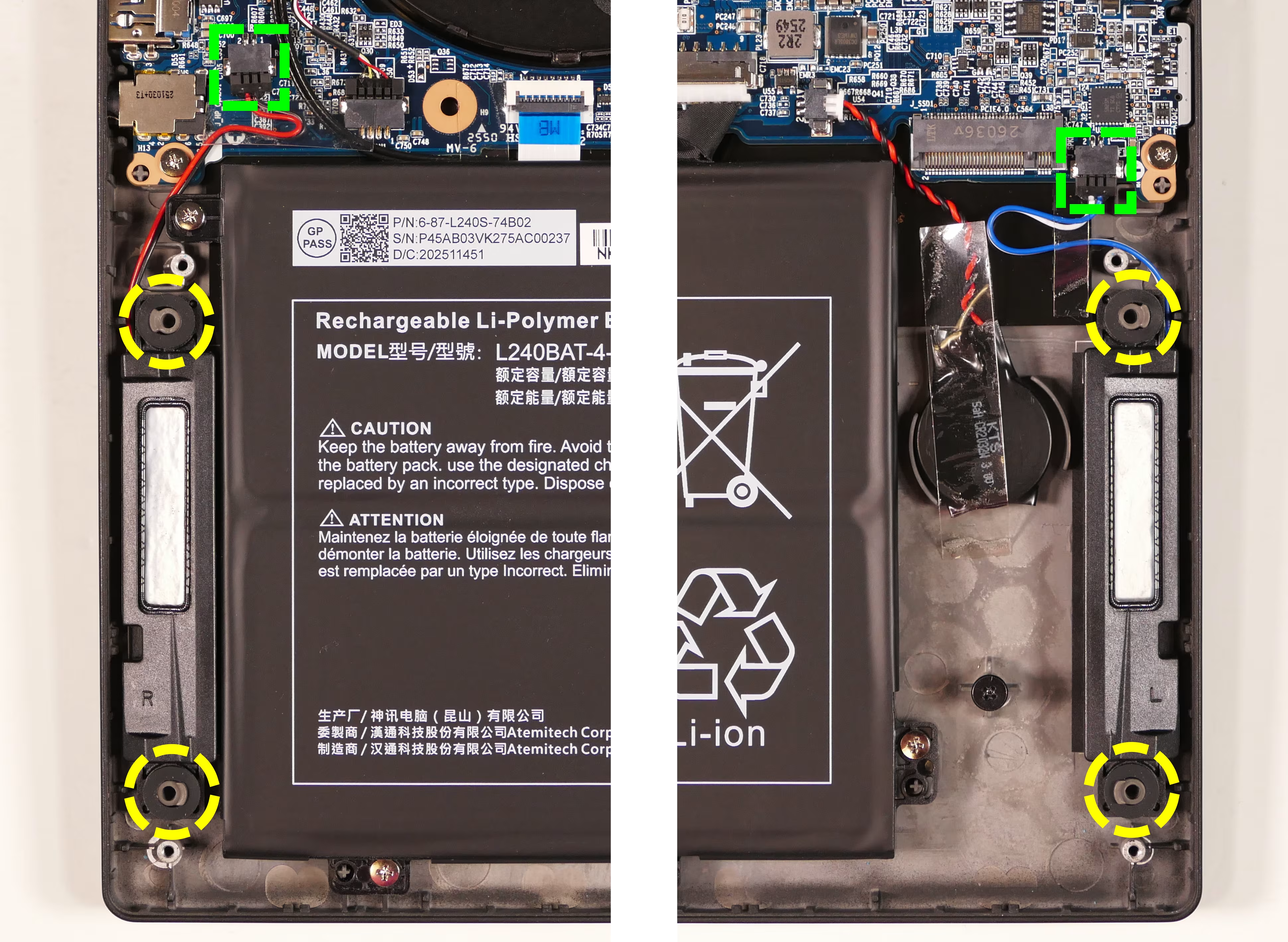
- Disconnect the black speaker connector(s) from the motherboard, removing any clear tape as necessary to free the wire(s).
- Slide the new speaker(s) onto the mounting posts and connect the speaker connector(s).
- The right speaker (shown on the left above) connects to
J_SPKR2. - The left speaker (shown on the right) connects to
J_SPKL2.
- The right speaker (shown on the left above) connects to
- Reinstall the bottom cover.