Internal Overview
Thelio Major B1
Section titled “Thelio Major B1”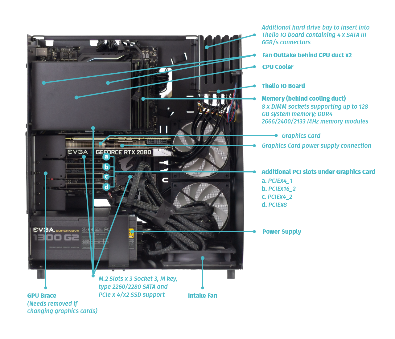
Thelio Major B2
Section titled “Thelio Major B2”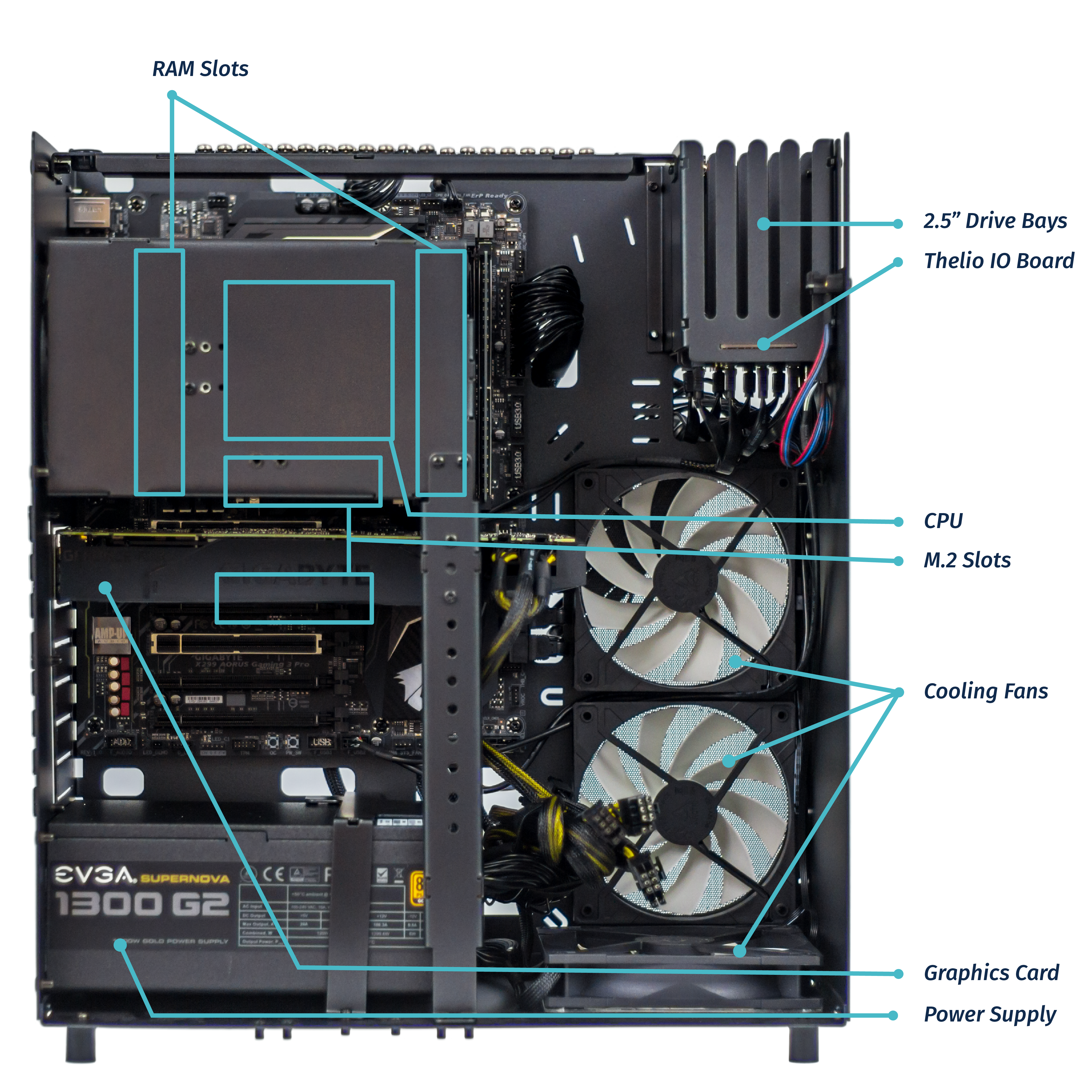
Thelio Major R1
Section titled “Thelio Major R1”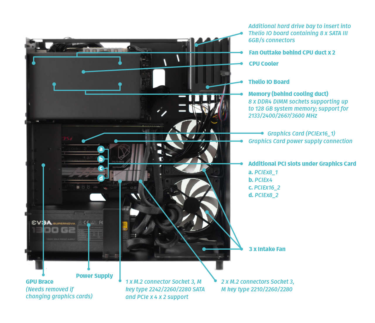
Thelio Major R2
Section titled “Thelio Major R2”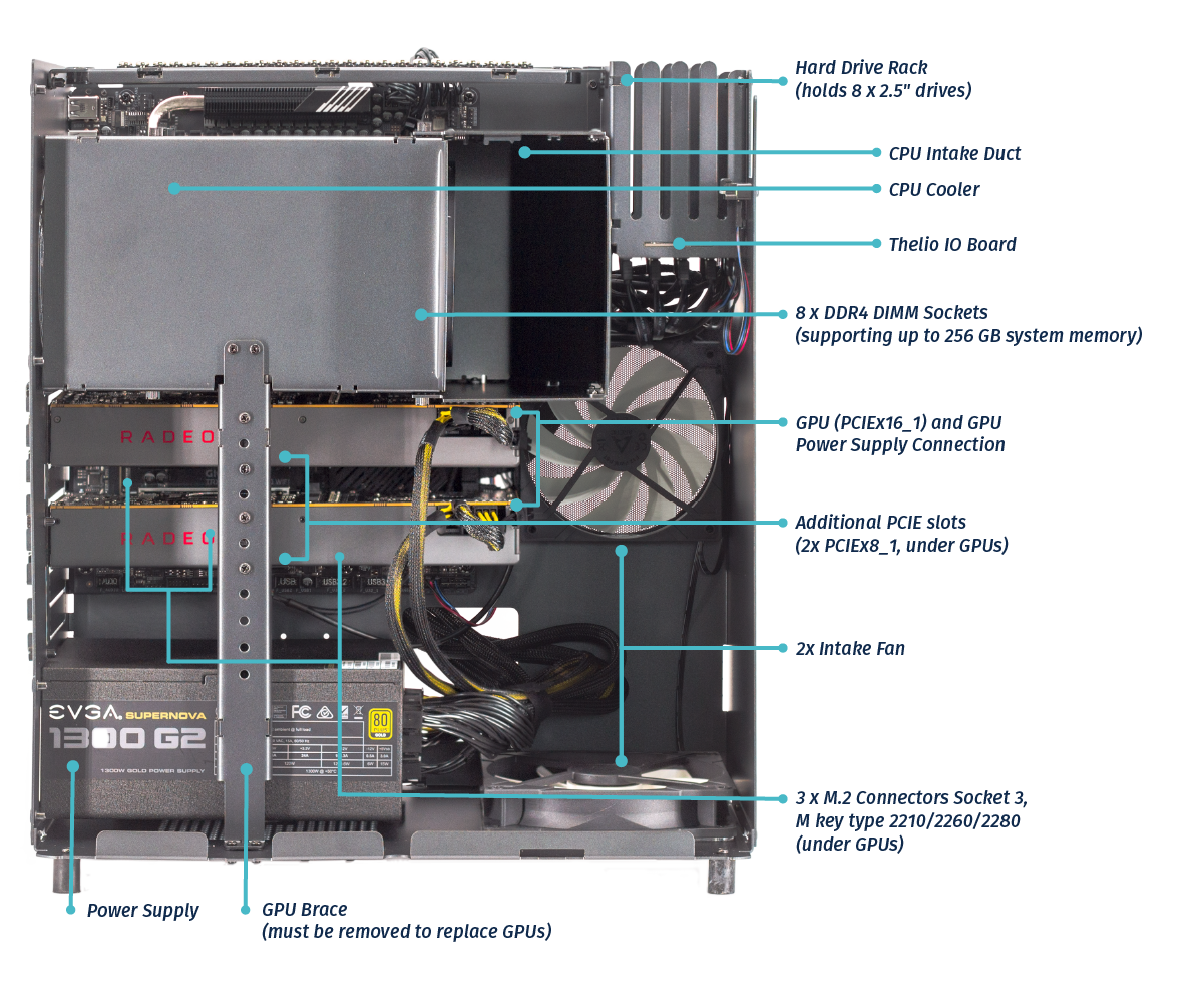
Power Switch Connections Overview
Section titled “Power Switch Connections Overview”The Thelio power button is wired as in the diagram and photo.
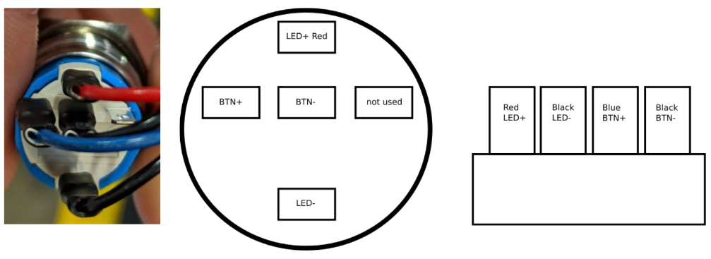
Fig. 12: Close up of Thelio power switch wiring (left). Thelio power switch Wiring Diagram (right).
Thelio IO Board
Section titled “Thelio IO Board”USB IO The USB connector has a row of 5 and a row of 4 holes for pins. You want to use the row of 4 holes with the red wire to the left. For reference, this is the pinout:
| 5V | D- | D+ | GND | None |
|---|
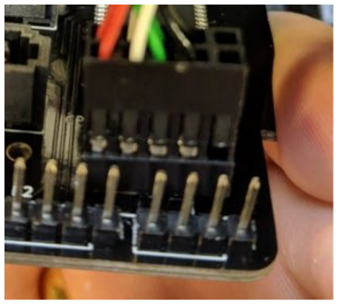
Fig. 13: Thelio IO Board Pinout.
IO Power button
Section titled “IO Power button”The button is connected to the left side and the motherboard on the right. Both are connected with the solid plastic side facing the edge. This is the pinout:
| Button | LED+ | LED- | BTN+ | BTN- |
|---|---|---|---|---|
| Board | LED+ | LED- | BTN+ | BTN- |
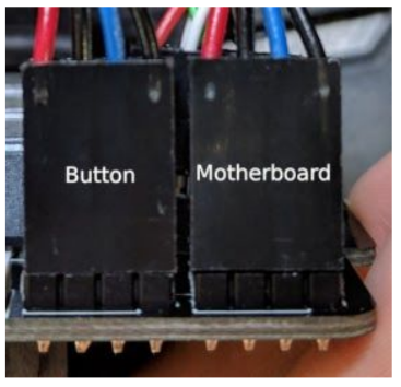
Fig. 14: Power Button and Motherboard power connectors attached to Thelio IO board.
Fig. 15: Thelio internal power switch (underside of the Thelio IO board).
The Thelio IO power button can be used to power on the Thelio when the top case is removed. The button is located on the underside of the Thelio IO Board (Fig. 15, above).
Motherboard Power button
Section titled “Motherboard Power button”The motherboard power button is connected on the part of the front panel header missing a pin. Due to a design oddity of motherboards used for Thelio, the positive and negative power button lines must be flipped.
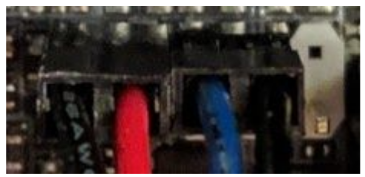
Fig. 16: Motherboard power button and Thelio Power Button connections.
This is the pinout:
| LED- | LED+ | BTN+ | BTN- | None |
|---|