

Adder Pro (Parts & Repairs)
Many components in your Adder Pro can be upgraded or replaced as necessary. Follow these step-by-step guides for instructions.
Removing the bottom cover:
Section titled “Removing the bottom cover:”Removing the cover is required to access the internal components. Prior to removing the cover, ensure the AC power is unplugged and all peripherals (such as USB drives) are unplugged or removed from the system.
Part numbers:
- Bottom panel:
6-39-L5503-012
Tools required: Cross-head (Phillips) screwdriver
Time estimate: 5 minutes
Difficulty: Easy ●
Steps to remove the bottom cover:
Section titled “Steps to remove the bottom cover:”- Place the machine lid-side down.
- Use a soft surface (such as a towel) to avoid scratches.
- Remove the 12 bottom panel screws.
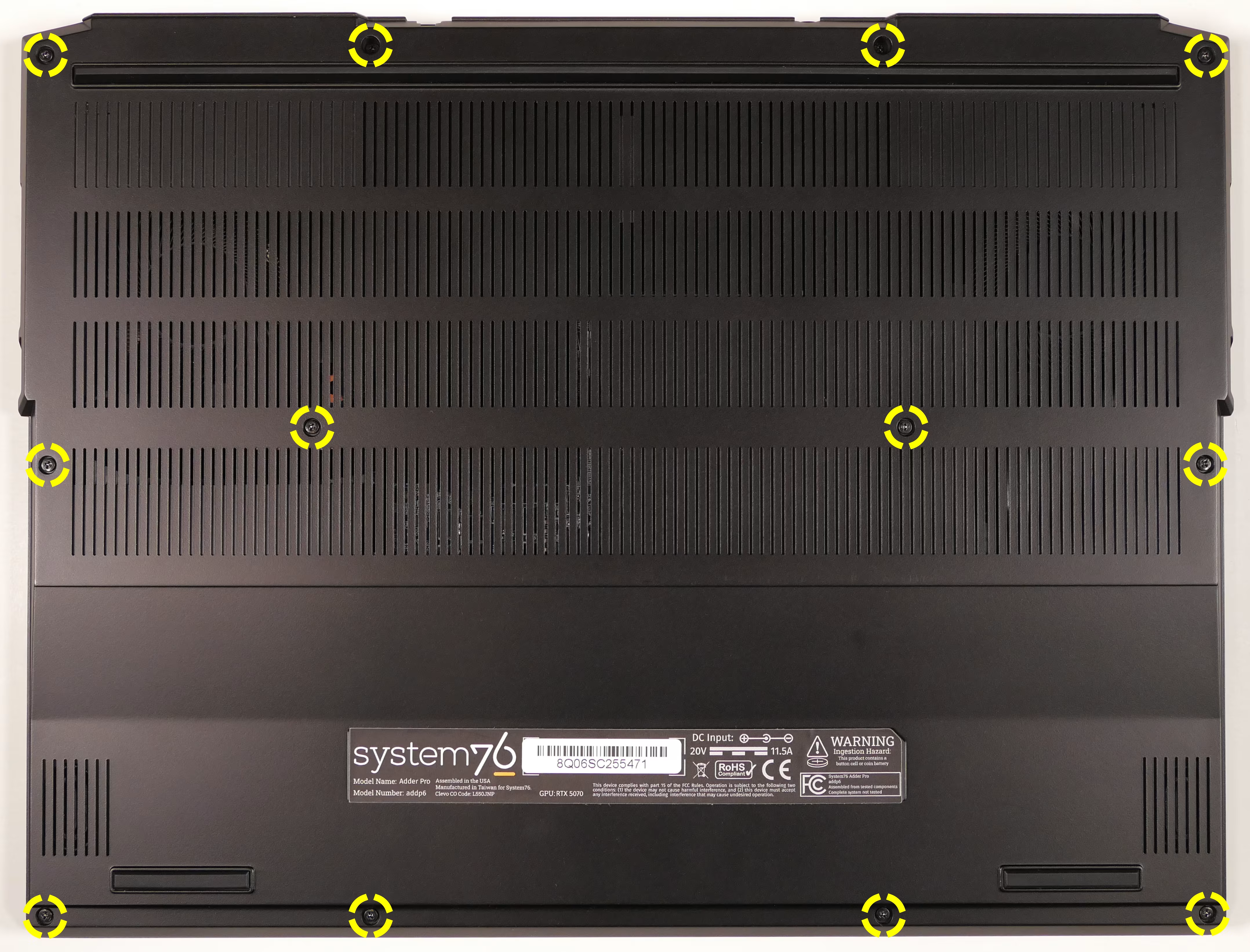
- Pull the bottom panel off, starting from the back corners.
- Grip the reflective tabs on the top of the chassis to separate it from the bottom cover, then pull at the sides of the bottom cover.
Replacing the RAM:
Section titled “Replacing the RAM:”The Adder Pro 6 supports up to 96GB (2x48GB) of DDR5 SO-DIMMs running at 5600MHz. If you’ve purchased new RAM, need to replace your RAM, or are reseating your RAM, follow these steps.
Tools required: Cross-head (Phillips) screwdriver
Time estimate: 10 minutes
Difficulty: Easy ●
Steps to replace the RAM:
Section titled “Steps to replace the RAM:”- Follow the steps above to remove the bottom cover.
- Press the small tabs on both sides of the RAM away from each other simultaneously. The RAM should spring up to an angle.
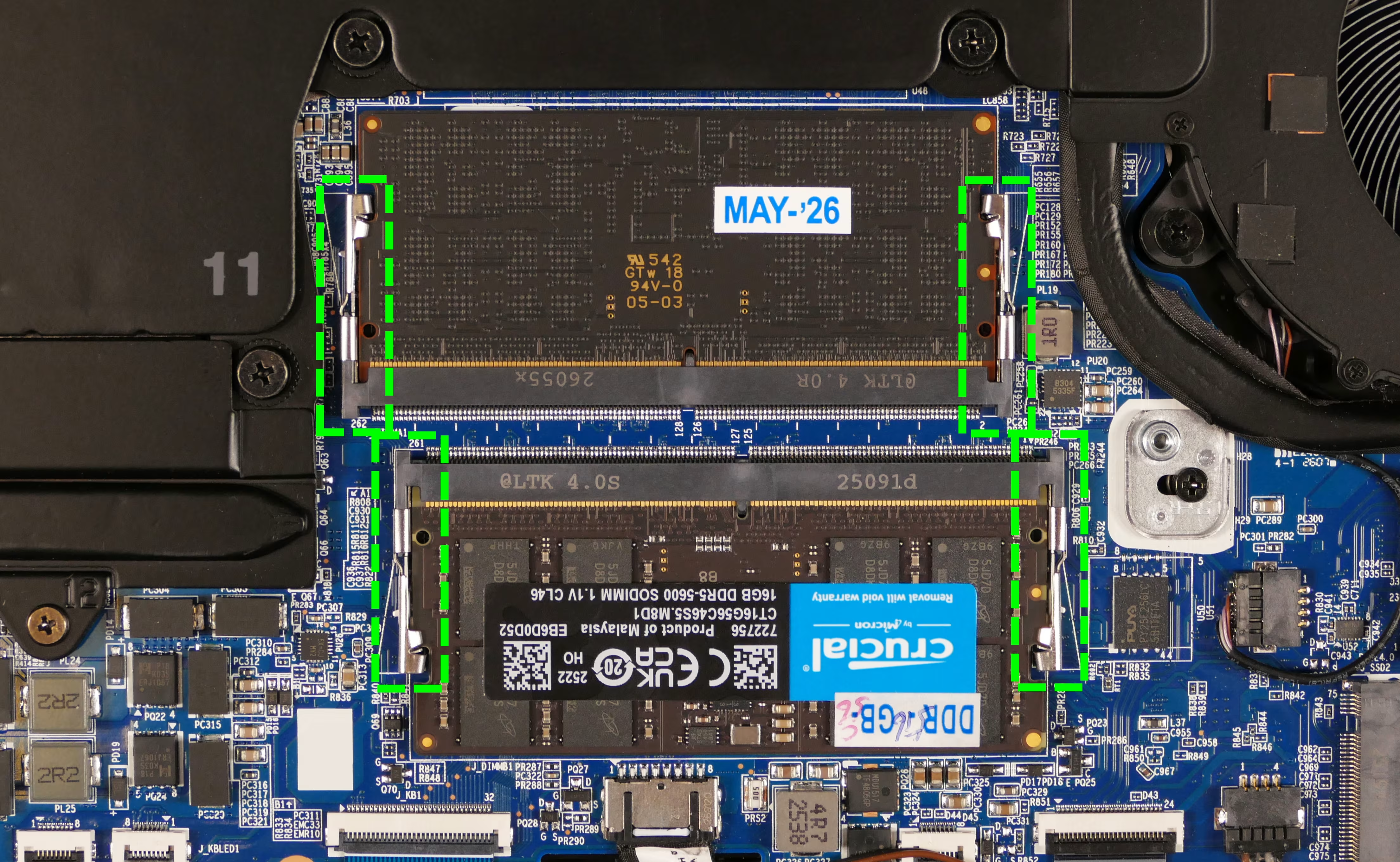
- Remove the RAM from the slot.
- Insert the new RAM (or reseat the existing RAM) by placing it in the keyed slot and pressing down on the RAM until it clicks into place.
Replacing an M.2/NVMe SSD:
Section titled “Replacing an M.2/NVMe SSD:”This model supports up to two M.2 SSDs connected via PCIe NVMe Generation 4. Slot 1 supports size 2280, while Slot 2 supports size 2242. (Smaller sizes can be used in larger slots using adapter brackets.)
Tools required: Cross-head (Phillips) screwdriver
Time estimate: 10 minutes
Difficulty: Easy ●
Steps to replace an M.2 drive:
Section titled “Steps to replace an M.2 drive:”- Follow the steps above to remove the bottom cover.
- Remove any thermal tape from the top of the drive (shown on the Slot 1 drive below).
- Peel slowly to avoid breaking the thermal tape.
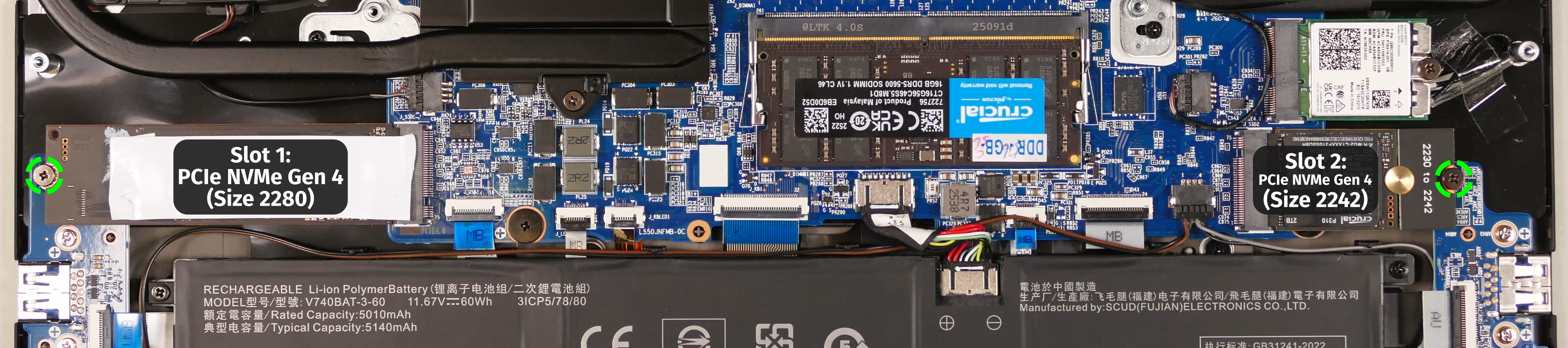
- Unscrew the retainer screw opposite the M.2 slot.
- Remove the existing M.2 drive by pulling it out of the slot.
- If an adapter bracket was being used (such as for the Slot 2 drive shown above), it can be removed from the old drive and (if necessary) transferred to the new drive.
- Insert the new M.2 drive into the slot and hold it in place.
- Replace the retainer screw.
- Optionally, place the thermal tape back onto the new drive.
- If thermal tape was not installed on the included drive, then it may have been included separately in the Adder Pro’s box.
Replacing the battery:
Section titled “Replacing the battery:”The battery provides primary power whenever the system is unplugged.
Because the Adder Pro 6 doesn’t have a CMOS battery, the main battery is also used to power the RTC (real-time clock) and the memory storing the UEFI setup (BIOS) settings. If the battery is completely drained or unplugged, the CMOS settings will reset.
Part numbers:
- The battery’s model number is
V740BAT-3-60, and the original part number is6-87-V74BS-63G01.- Third-party battery sellers may list one or both of these numbers, and may offer other compatible part numbers with the same model number.
- You can also contact System76 to purchase a replacement battery.
Tools required: Cross-head (Phillips) screwdriver
Time estimate: 10 minutes
Difficulty: Easy ●
Steps to replace the battery:
Section titled “Steps to replace the battery:”- Follow the steps above to remove the bottom cover.
- Remove the 4 battery screws from the corners of the battery casing.
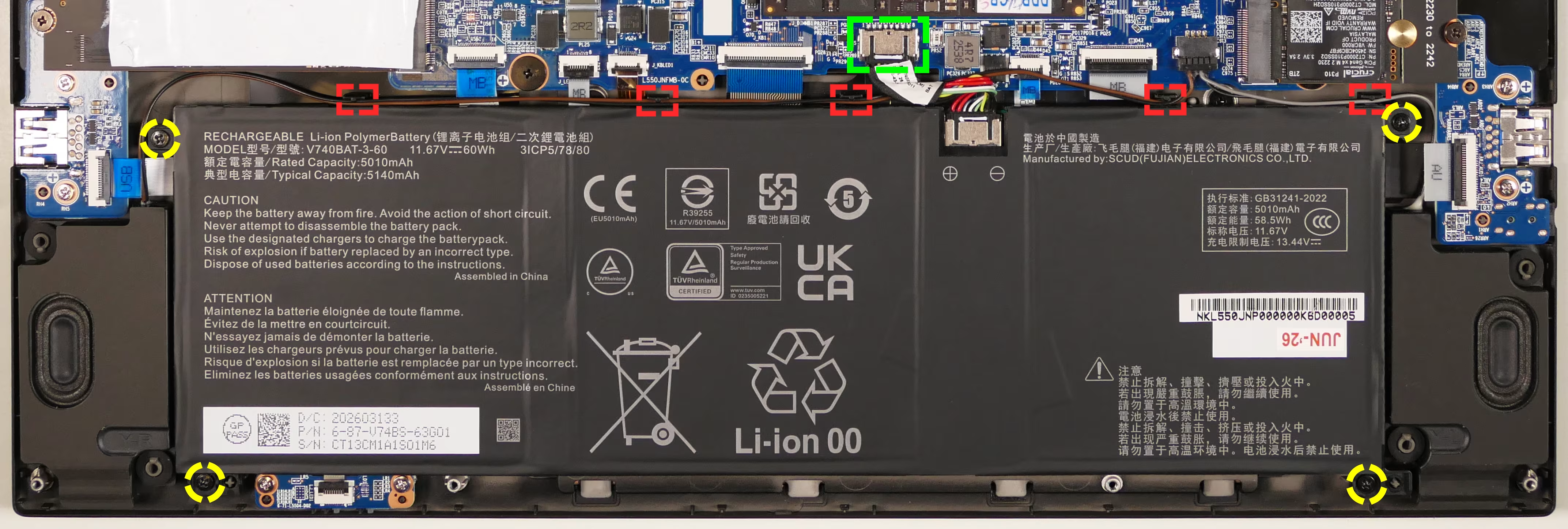
- Unplug the black connector from the motherboard’s
J_BAT1header. - Clear the black, brown, and grey speaker wires out of the plastic channels along the top edge of the battery (highlighted red above).
- Remove and replace the battery.
- Feed the black, brown, and grey speaker wires back through the plastic channels along the top edge of the new battery.
- Screw in the new battery.
- When plugging in the new battery, the black wire on the connector goes on the left, and the red wire goes on the right (with the battery connector’s white label facing up).
Replacing the wireless card:
Section titled “Replacing the wireless card:”Your Adder Pro’s WiFi and Bluetooth are both handled by the same module. It is a standard M.2 2230 slot with PCIe and USB interfaces (E-key).
Part number:
- The standard wireless card is an Intel
BE211.
Tools required: Cross-head (Phillips) screwdriver
Time estimate: 10 minutes
Difficulty: Medium ●
Steps to replace the WiFi/Bluetooth module:
Section titled “Steps to replace the WiFi/Bluetooth module:”- Follow the steps above to remove the bottom cover.
- Unscrew the wireless card screw holding the card and its wire bracket in place.
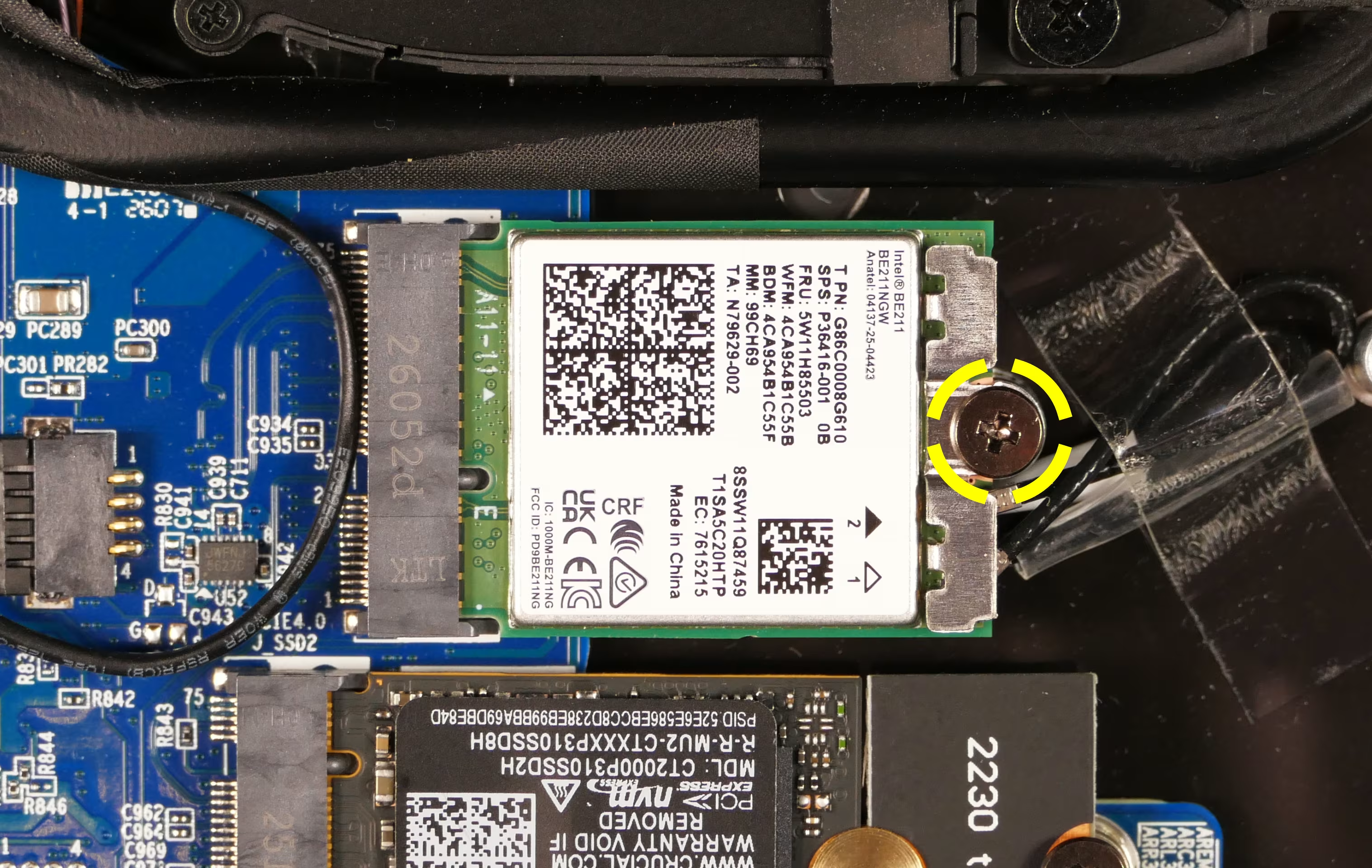
- Remove the metal bracket that holds the wires onto the card.
- Gently remove the two antennas (highlighted red below) by pulling them up and away from the wireless card. The card will pop up at an angle.
- Pull back the clear tape as necessary to maneuver the antenna wires.
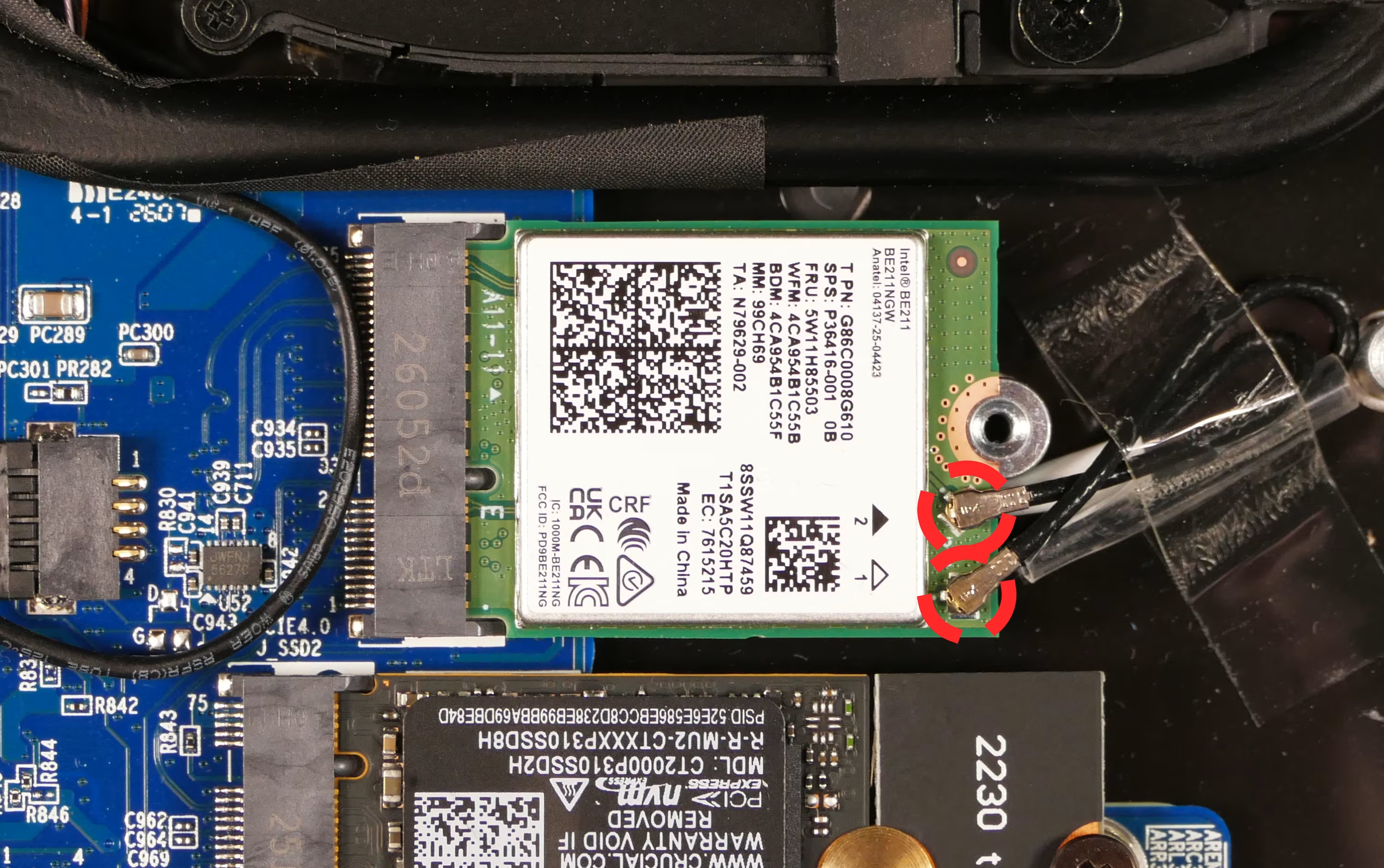
- Slide the card out of the M.2 slot.
- Insert the new wireless card into the M.2 slot at a 30-degree angle.
- While holding the card down against the screw hole, attach the two antennas by aligning the circular fittings and pressing onto the wireless card. The connectors will snap into place.
- Use caution when attaching the connectors; the pins can bend, break, or snap.
- Reinstall the metal bracket and the retaining screw.
- Reinstall the bottom panel.
Replacing the cooling system:
Section titled “Replacing the cooling system:”The Adder Pro 6 has a single heatsink assembly with two fans. This assembly cools the CPU and GPU.
If the fans become noisy and cleaning them out doesn’t fix the issue, you may need a new fan. Contact support to start a warranty claim or parts purchase. These instructions can also be used if physical damage to the heatsink necessitates its replacement.
Thermal paste helps facilitate effective heat transfer between the CPU/GPU and the cooling equipment; depending on your climate and the age of the machine, replacing the thermal paste may improve cooling performance. The thermal paste should generally be replaced whenever the heatsink is removed.
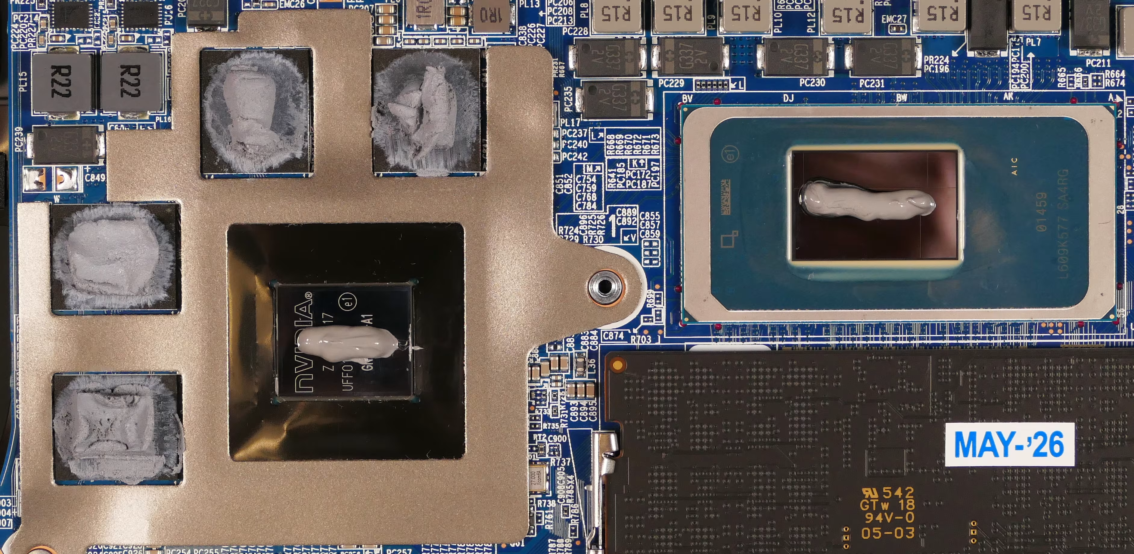
Thermal putty (thicker than thermal paste) is used to bridge the gap between the VRAM chips and the heatsink. Replacing the thermal putty is optional when removing the heatsink. System76 suggests Thermal Grizzly Putty Basic (available at various retailers) or a similar alternative.
Part numbers:
- Fan/heatsink assembly: Yingfan
6-31-L550N-102 - Left fan: Yingfan
5L5 - Right fan: Yingfan
5L6
Tools required: Cross-head (Phillips) screwdriver, thermal putty spreader (flat plastic tool)
Time estimate: 25 minutes
Difficulty: High ●
Steps to replace the heatsink/thermal paste:
Section titled “Steps to replace the heatsink/thermal paste:”- Follow the steps above to remove the bottom cover.
- Remove the twelve heatsink and fan screws in order of the stamped and printed numbers, starting with #1, then #2, and continuing until you have removed #12.
- The fan screws (#1-5) and the silver heatsink screw (#12) are held captive, and will not completely detatch from the heatsink/fans. The black heatsink screws (#6-#12) are not held captive, and will come loose when untightened.
- Do not remove the smaller black screws holding the fan covers onto the fans.
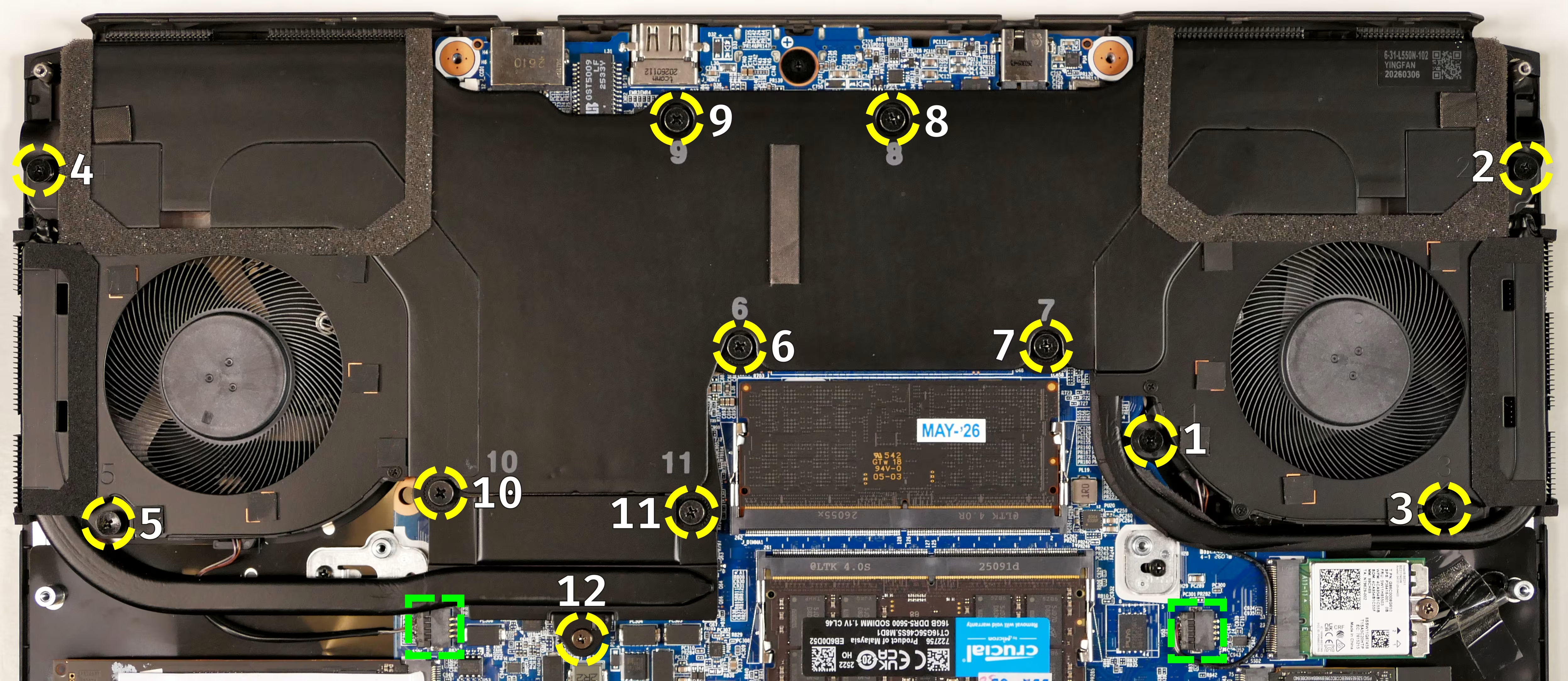
- Unplug the two fan connectors from the motherboard (highlighted green above).
- Remove the heatsink/fans from the case, being careful not to bend the heatsink pipes. It may take some pressure to break the seal of the thermal paste.
- Using a paper towel, remove the existing thermal paste from the CPU, GPU, and heatsink. You may also use a small amount of rubbing alcohol if the old paste is dried or difficult to remove.
- You can optionally remove the thermal putty from the four VRAM chips surrounding the GPU chip if you have replacement thermal putty to install.
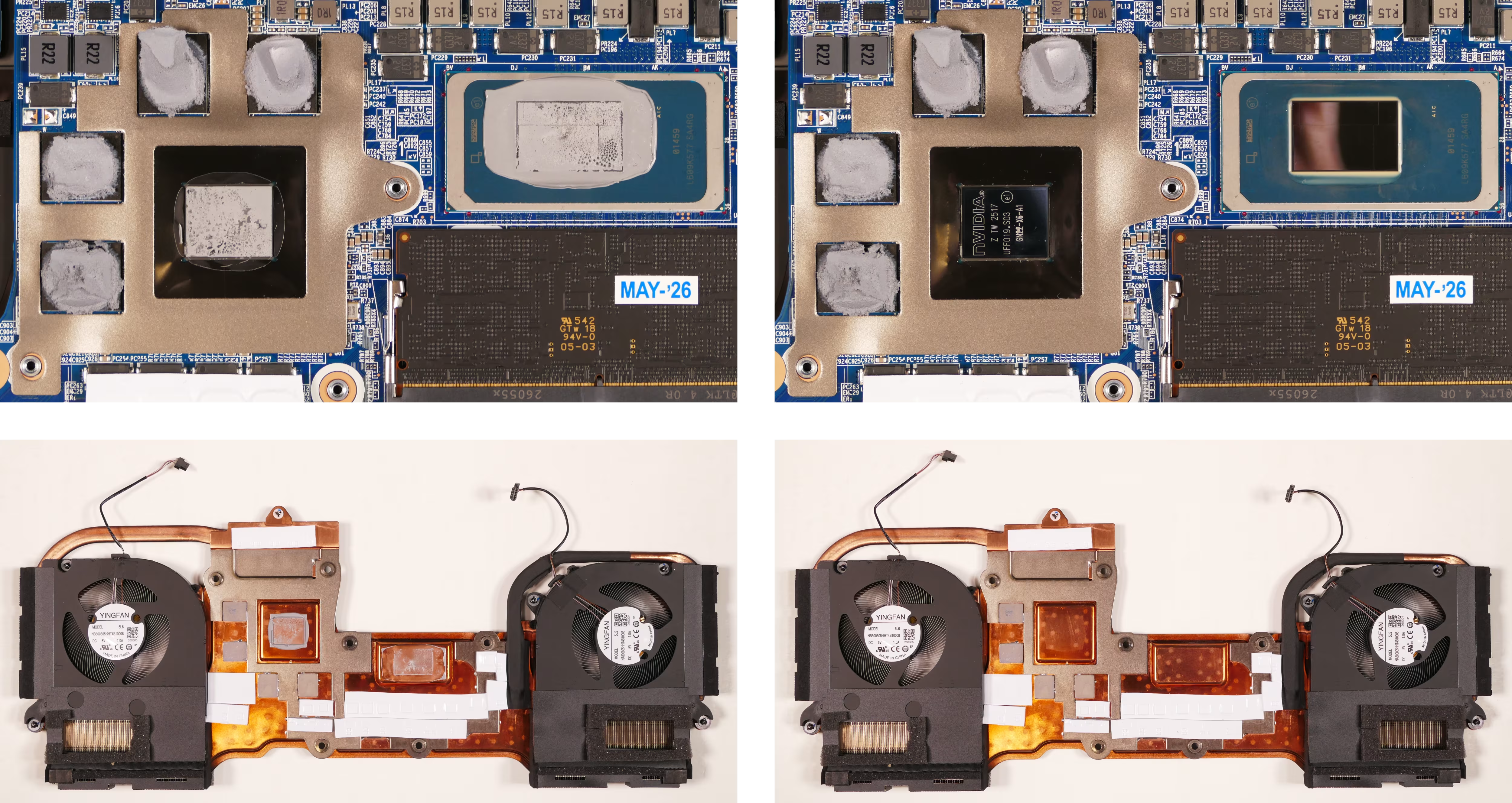
- Apply a small line of thermal paste directly onto the CPU chip and the GPU chip.
- If you’re also replacing the thermal putty, apply the new putty to the four VRAM chips.
- If you aren’t replacing the thermal putty, scoop the existing putty (from the VRAM chip and the corresponding location on the heatsink) into the center of each VRAM chip using a flat plastic tool.
- Carefully place the heatsink back into position.
- Reinstall the fan and heatsink screws, starting with #1, then #2, and so on until #12.
- Plug the two black fan connectors back into the motherboard.
Replacing the speakers:
Section titled “Replacing the speakers:”The system has two bottom-firing speakers, which can be removed and replaced as a pair.
Part numbers:
- The part number for the pair of speakers is
6-23-5L550-0S1.
Tools required: Cross-head (Phillips) screwdriver
Time estimate: 10 minutes
Difficulty: Easy ●
Steps to replace the speakers:
Section titled “Steps to replace the speakers:”- Follow the steps above to remove the bottom cover.
- Pull the speakers off of the plastic posts.
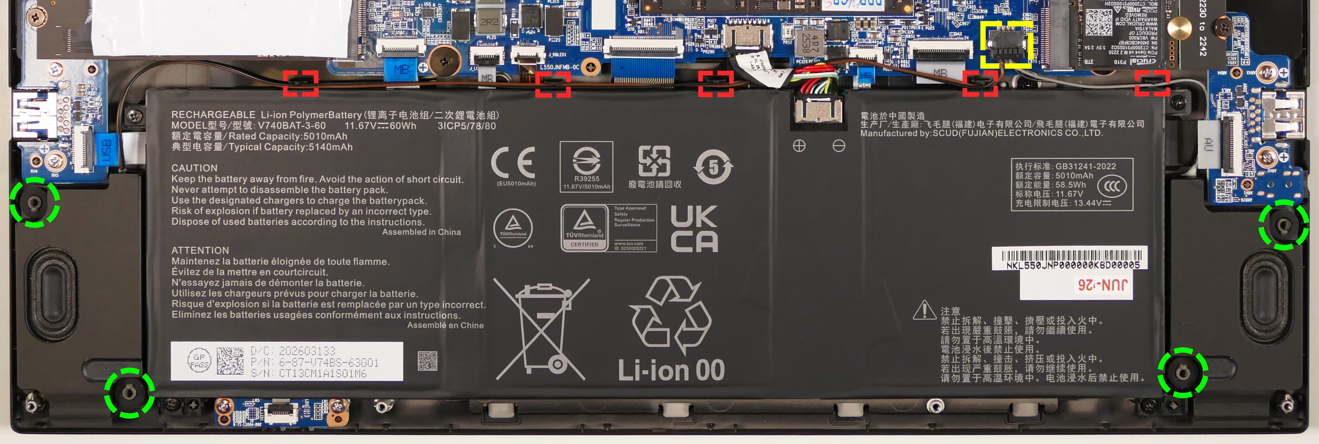
- Disconnect the speaker connector from the motherboard’s
J_SPKR1header. - Remove the old speakers from the chassis, freeing their wires from the plastic channels along the top edge of the battery.
- Connect the new speakers to the motherboard, place them onto the plastic posts, and push their wires into the plastic channels along the top edge of the battery.
- Reinstall the bottom cover.