Thelio Major (Parts & Repairs)
Many components in your Thelio Major can be upgraded or replaced as necessary. This page uses photos of the the R5-N4 revision, which indicates:
- R5: The fifth AMD motherboard used in Thelio Major.
- N4: Based on the fourth revision of the nebula40 chassis.
Minor case details may vary based on the production date of the unit, but screw counts, general component locations, and other details should remain the same unless otherwise noted.
Power the machine off, switch off the power supply, and unplug all peripherals before working with any internal components.
Removing the side panels:
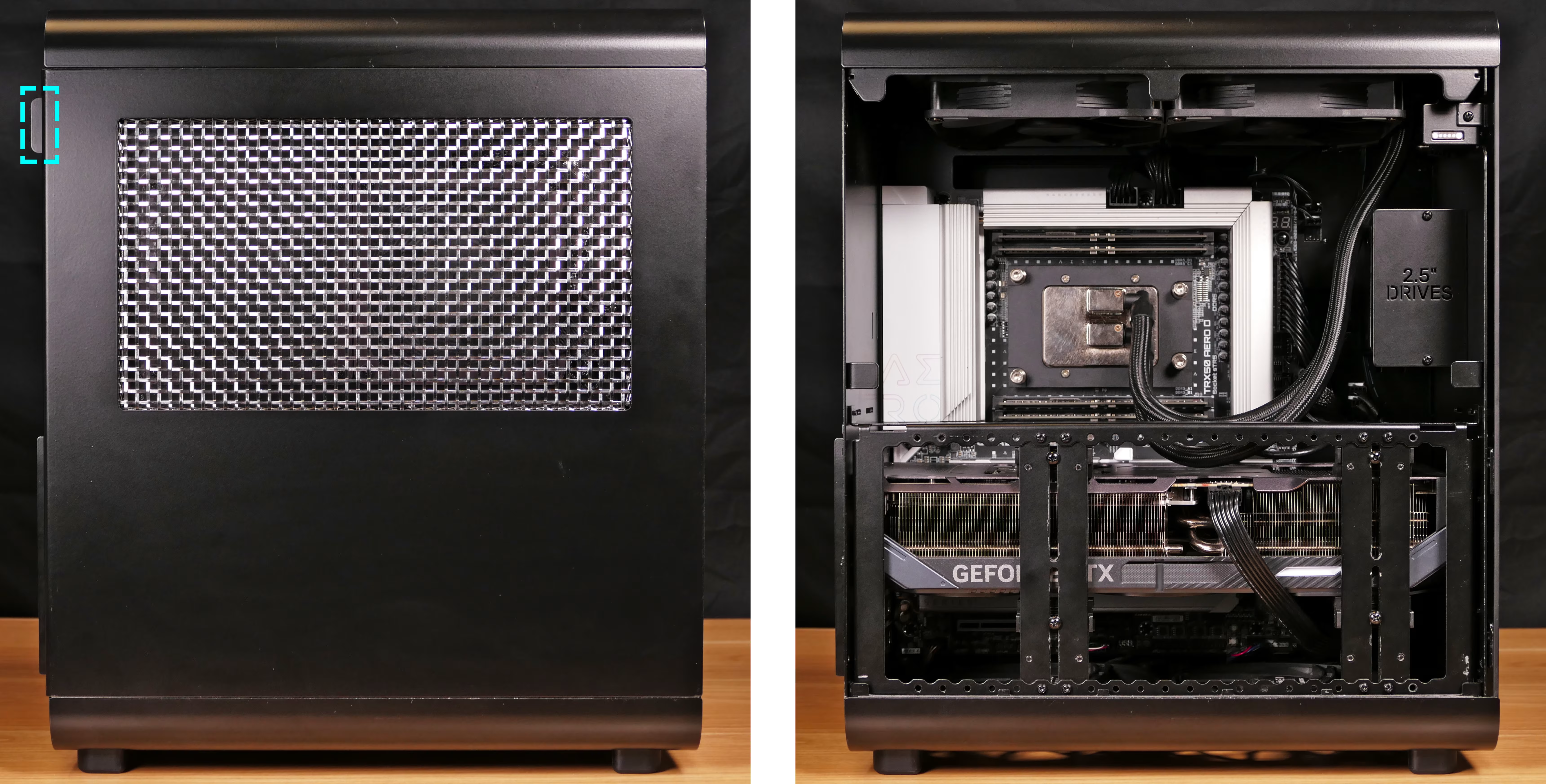
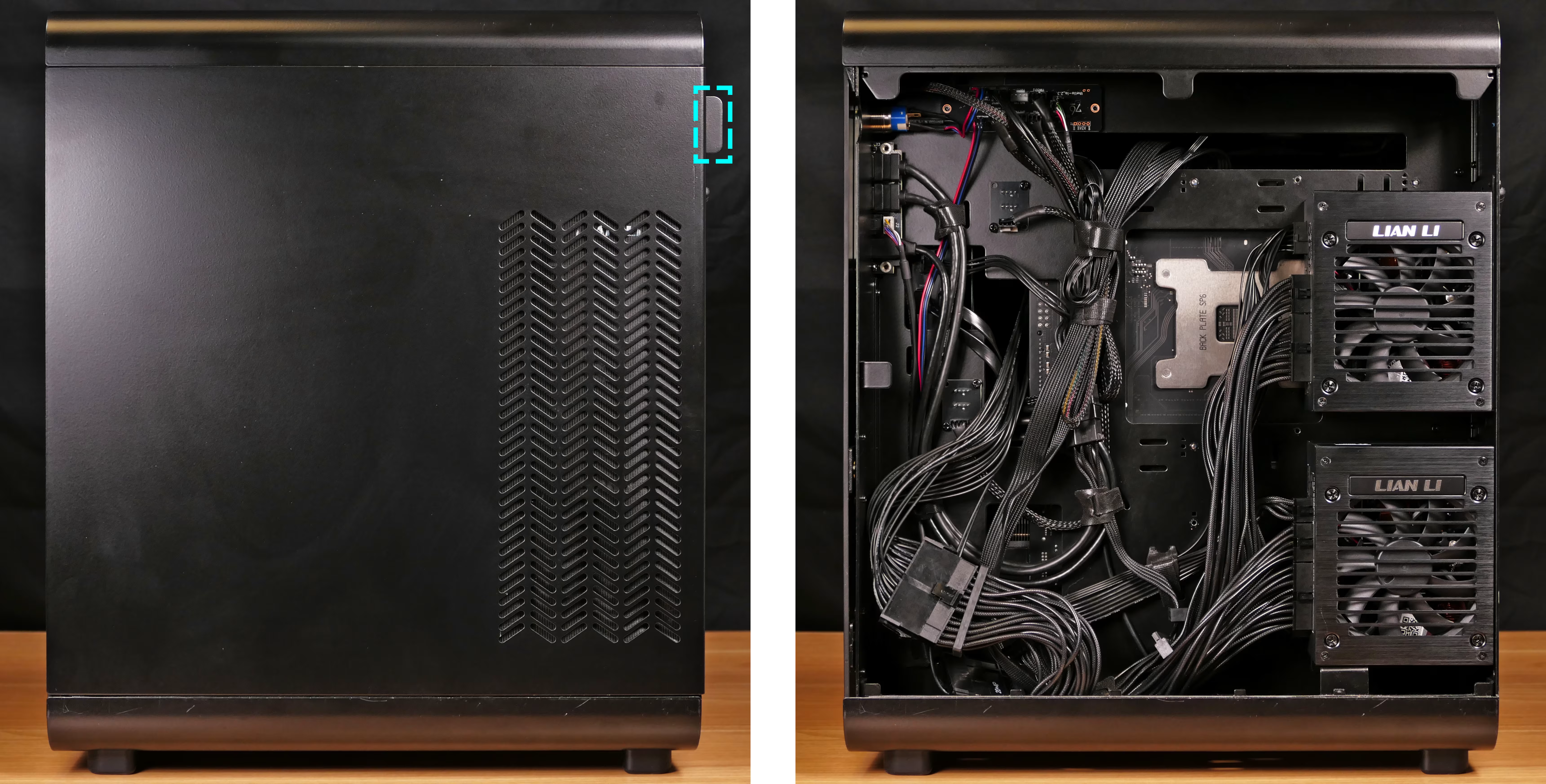
Section titled “Removing the side panels:”The side panels can be removed to access the internal components.
- The left side panel (with a mesh window) covers the motherboard, RAM, M.2 SSDs, and PCI Express cards.
- The right side panel (without a window) covers the power supply (or supplies), Thelio Io board, and front I/O.
Tools required: Cross-head (Phillips) screwdriver (optional)
Time estimate: 2 minutes
Difficulty: Easy ●
Steps to remove the left side panel:
Section titled “Steps to remove the left side panel:”- Remove the two back thumbscrews holding the side panel onto the machine.
- The left side panel’s screws are on the right when viewed from the back of the machine.
- Starting from the tab at the upper back, pull the side panel off of the machine.
Steps to remove the right side panel:
Section titled “Steps to remove the right side panel:”- Remove the two back thumbscrews holding the side panel onto the machine.
- The right side panel’s screws are on the left when viewed from the back of the machine.

- Starting from the tab at the upper back, pull the side panel off of the machine.
Removing the front glass:
Section titled “Removing the front glass:”The front glass panel can be removed to access the screws and velcro cutouts underneath.
Tools required: Cross-head (Phillips) screwdriver
Time estimate: 4 minutes
Difficulty: Easy ●
Steps to remove the front glass:
Section titled “Steps to remove the front glass:”- Follow the steps above to remove the left and right side panels.
- Unscrew the bracket screw behind the top left of the front glass (at the top right when looking from the left side).
- Pull the front glass off from the cutouts at the top.
Removing the top shell:
Section titled “Removing the top shell:”The top shell of the chassis can be removed to access the 2.5“ drive screws.
Tools required: Cross-head (Phillips) screwdriver
Time estimate: 6 minutes
Difficulty: Easy ●
Steps to remove the top:
Section titled “Steps to remove the top:”- Follow the steps above to remove the left and right side panels and remove the front glass.
- Unscrew the four screws (two on the front, and two on the back) holding the top of the chassis on.
- Pull the top shell off of the chassis.
- When reinstalling the top shell, ensure the ventilation cutouts are aligned with the radiator underneath.
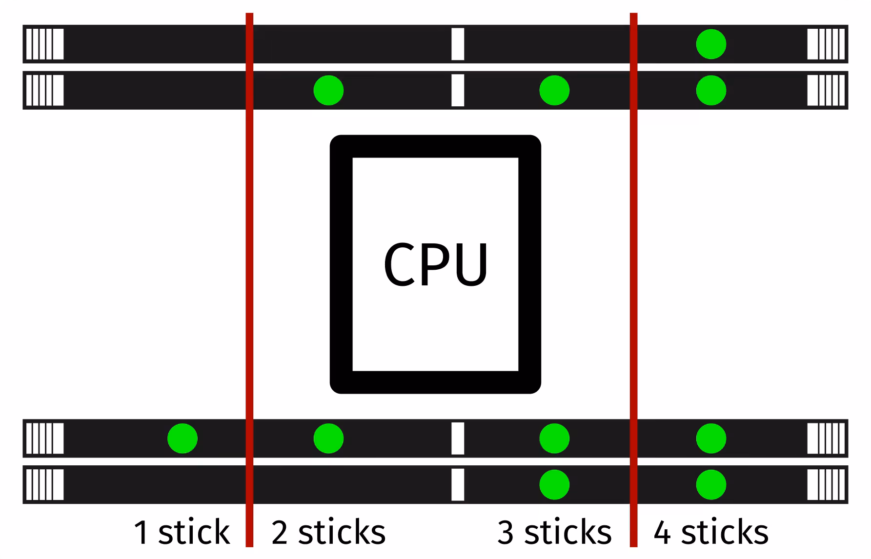
Replacing the RAM:
Section titled “Replacing the RAM:”Thelio Major R5-N4 supports up to 512GB (4x128GB) of ECC DDR5 RAM running at a speed of 5600 MHz. If you’ve purchased new RAM, need to replace your RAM, or are reseating your RAM, follow these steps.
Tools required: Cross-head (Phillips) screwdriver (optional)
Time estimate: 7 minutes
Difficulty: Easy ●
Steps to replace the RAM:
Section titled “Steps to replace the RAM:”- Follow the steps above to remove the left side panel.
- To remove an existing RAM stick, flip the left and right latches away from the stick, then pull the stick out of the slot.
- Make sure the tabs on the left and right of the slot are open (pulled away from the slot), then insert the new RAM (or re-seat the existing RAM) into the slot.
- The RAM stick will only fit in one direction. The larger group of pins goes on the left.
- Push near the left and right ends of the RAM stick until both tabs click shut.
- Use the following guide for placement of the RAM sticks:
- Replace the left side panel.
Replacing the GPU:
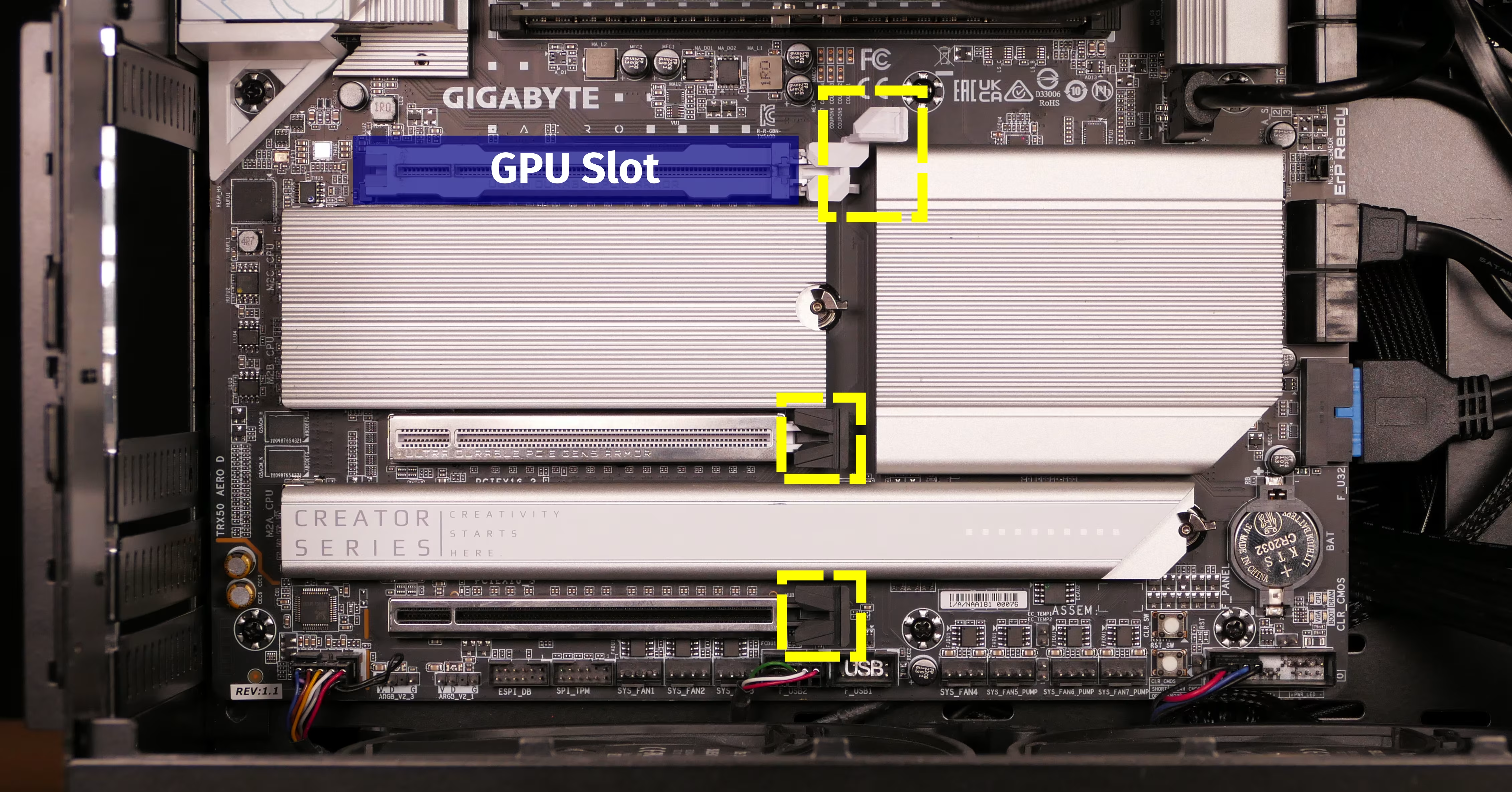
Section titled “Replacing the GPU:”Thelio Major ships with a dedicated GPU in the PCIe 5.0 x16 slot (top slot). GPUs greater than three slots tall may obstruct the lower PCIe slots.
Tools required: Cross-head (Phillips) screwdriver
Time estimate: 15 minutes
Difficulty: Medium ●
Steps to replace the GPU:
Section titled “Steps to replace the GPU:”- Follow the steps above to remove the left side panel and remove the front glass.
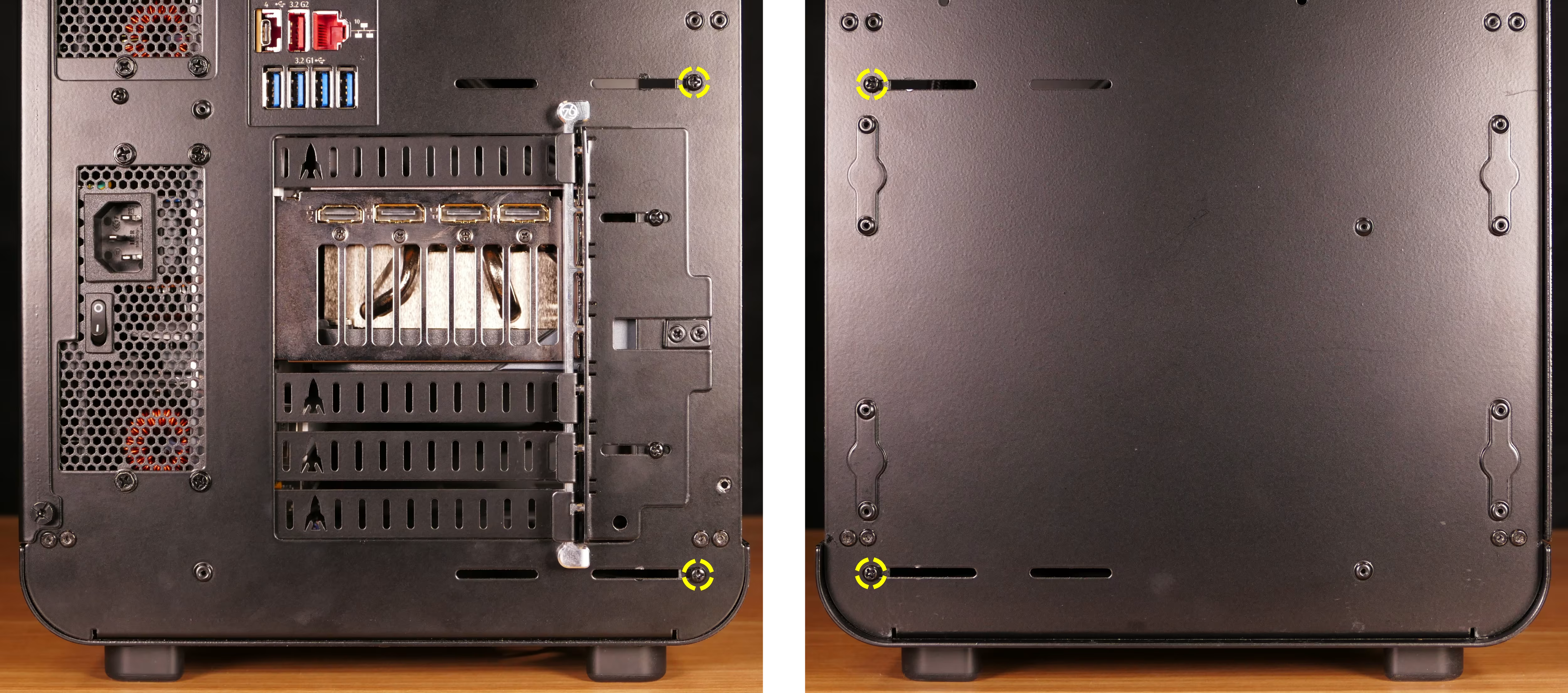
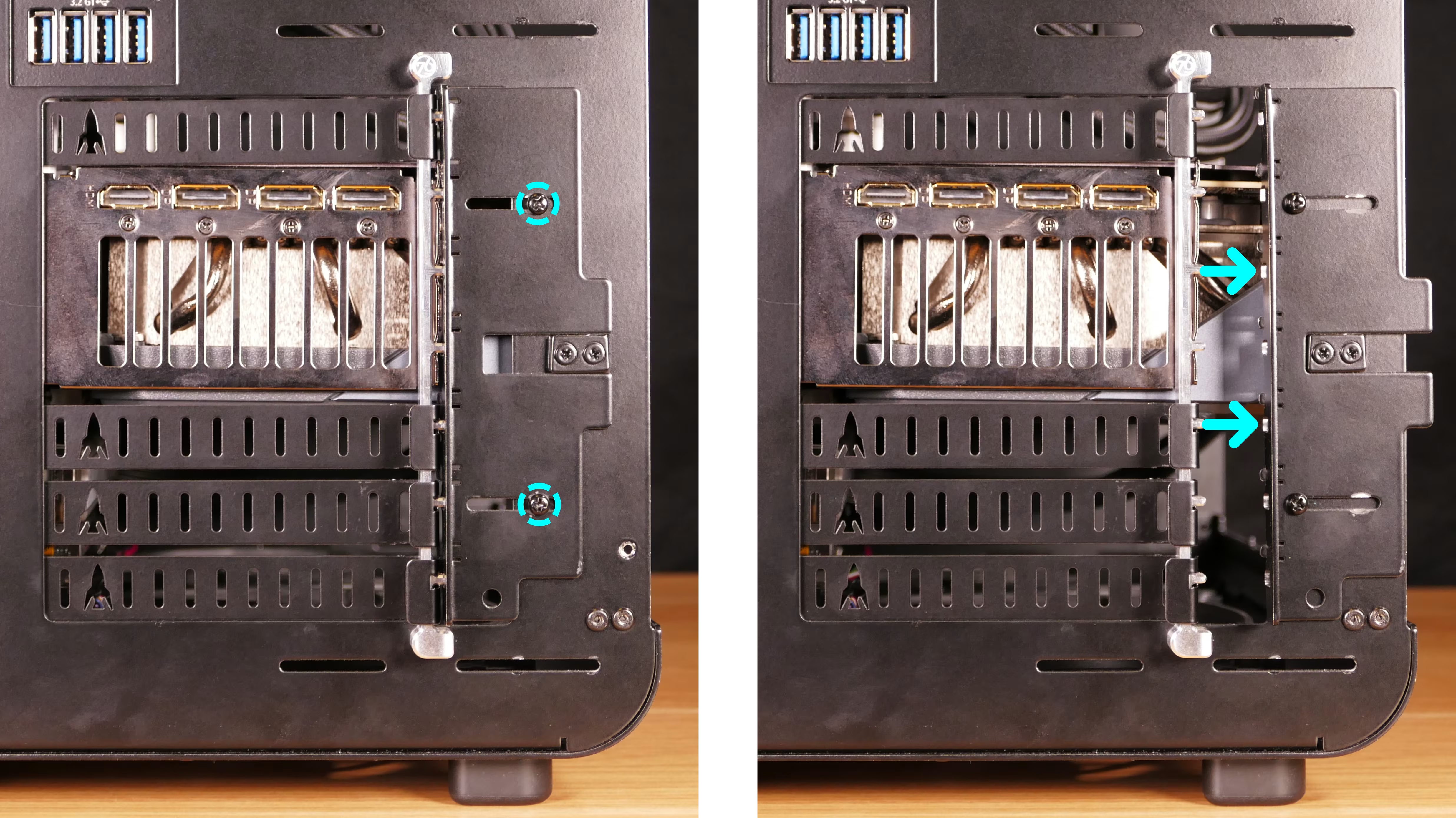
- Remove the four screws (two in the front, and two in the back) holding the GPU brace into the chassis.
- If necessary, loosen the four screws holding the four GPU fingers in place above and below the GPU, then slide the fingers away from the GPU.
- This step is necessary with large GPUs that require the GPU brace to be mounted near the edge of the chassis.
- Slide the GPU brace out of the chassis.
- Start by pivoting the top edge out of the chassis, then slide the bottom edge inward and upward until it can be removed from the chassis.
- Due to manufacturing tolerances, the GPU brace may require significant force to install and remove. Ensure the brace is not forcefully pressing against the GPU or any other non-chassis components when handling the brace.
- Unplug any power cables connected to the GPU.
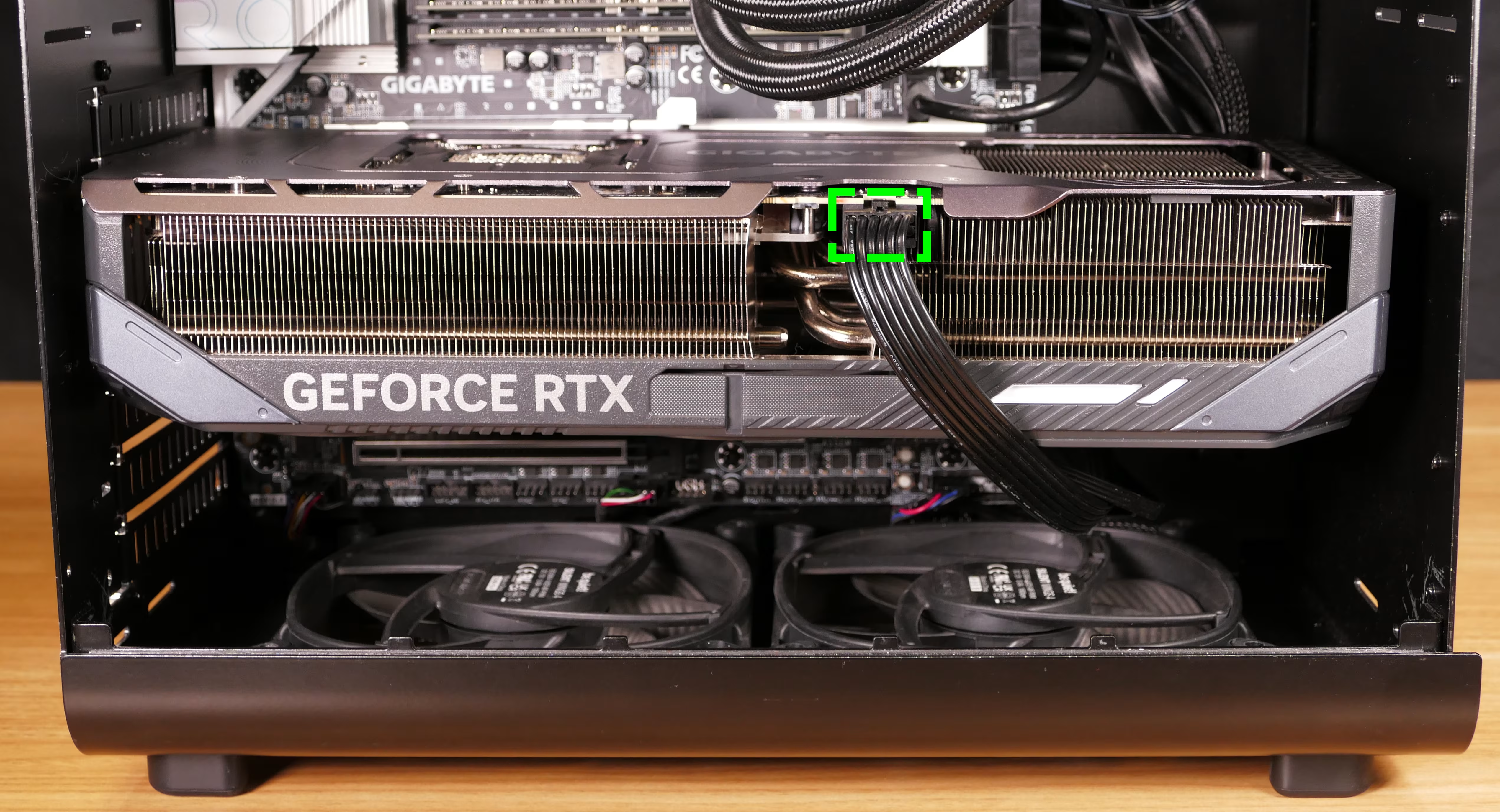
- Partially loosen the two back screws holding the PCIe bracket in place, and slide it into the rightmost position.
- While holding the GPU, push back the latch on the motherboard (accessible from above the GPU) to free the PCIe connection, then pull the card out of the slot.
- Insert the new GPU (or re-seat the existing GPU) into the top PCIe slot.
- Close the back PCIe bracket.
- Connect the GPU power cable.
- If necessary, adjust the position of the GPU brace fingers.
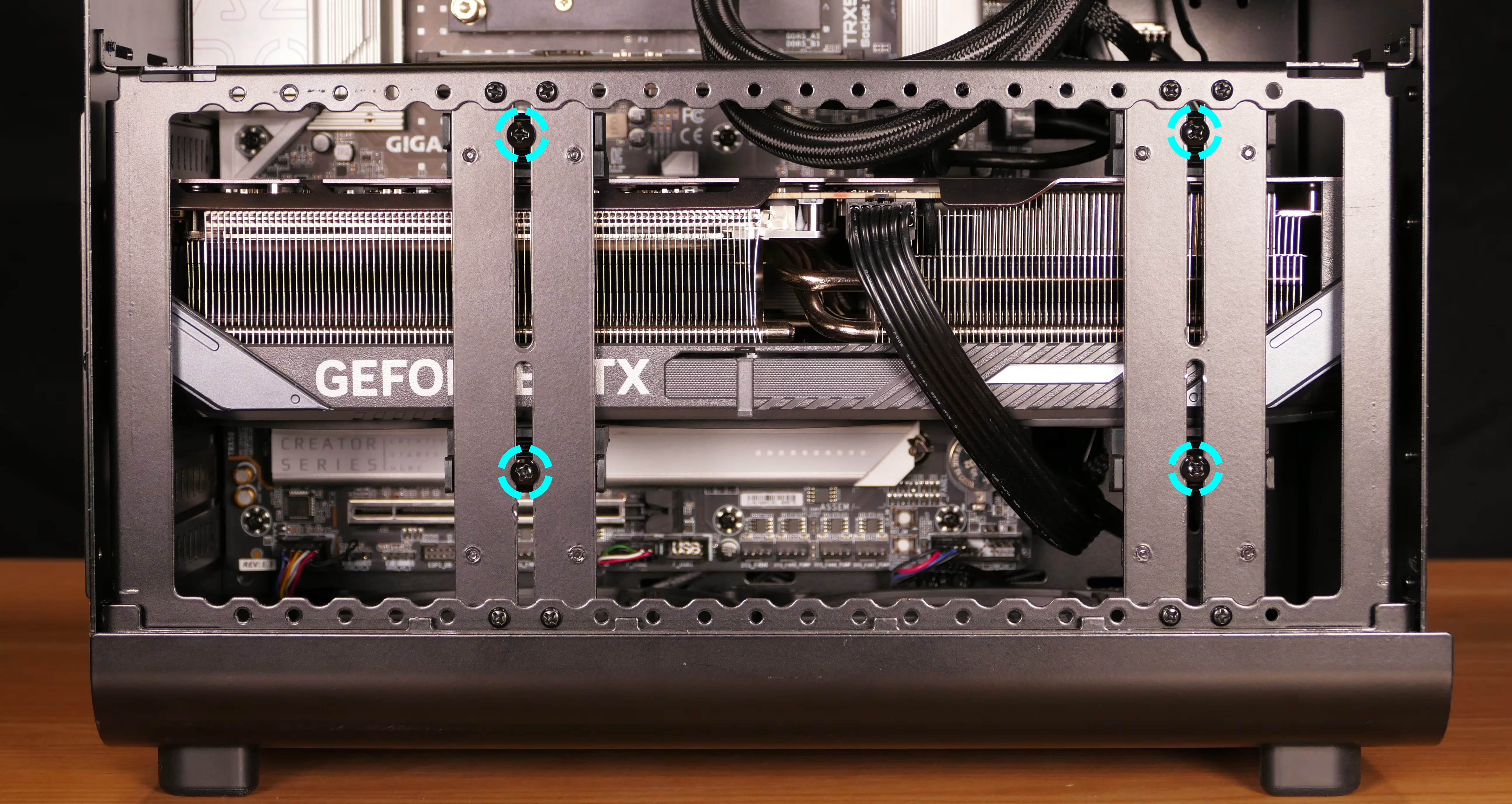
- To adjust the horizontal position of the brace fingers, use the screws at the top and bottom of the brace columns (highlighted red below).
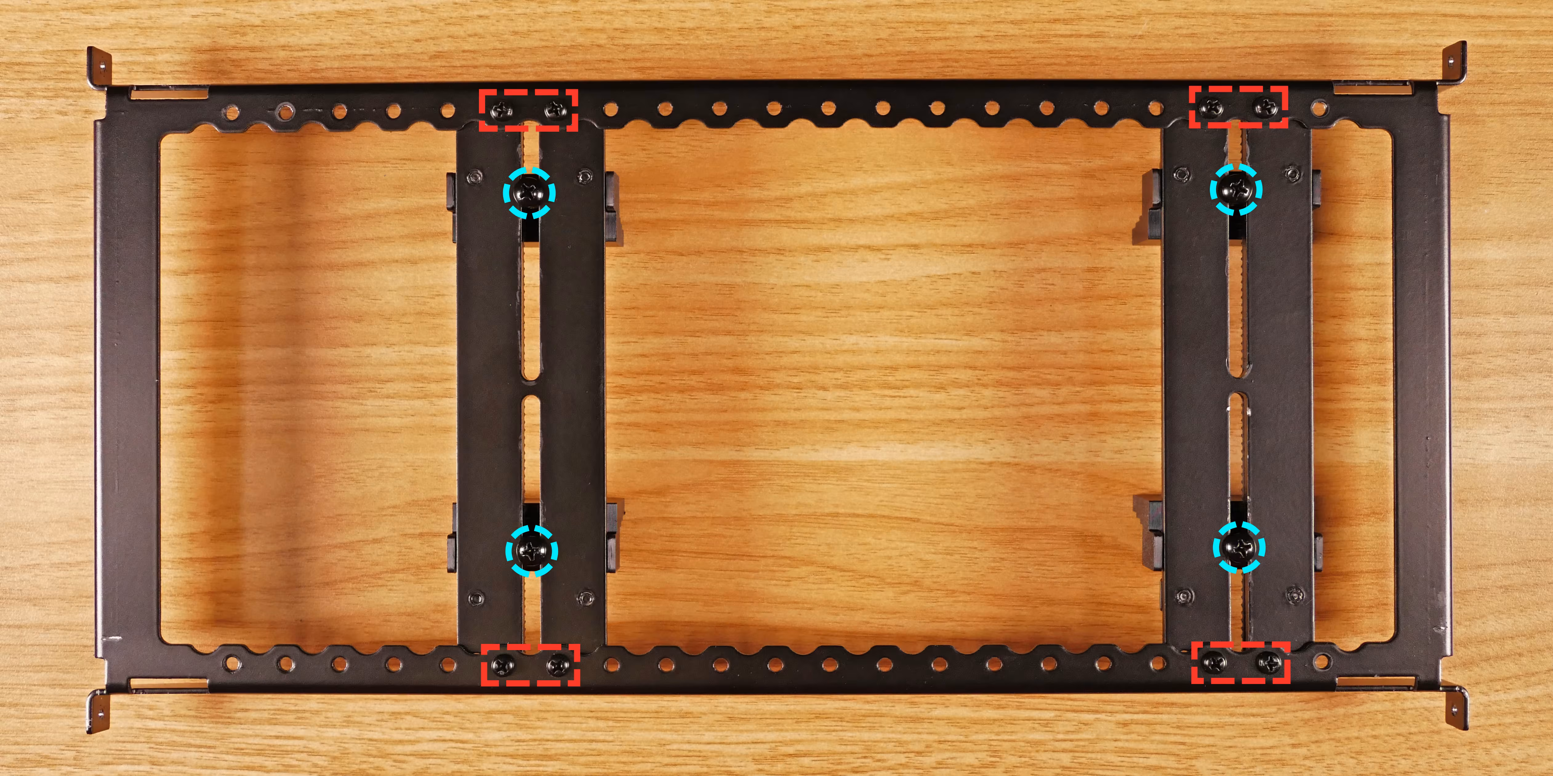
- To adjust the height of the GPU brace fingers, partially loosen each finger’s singular screw (highlighted cyan above), slide the finger to the appropriate height, and re-tighten the screw.
- For large GPUs, it may be necessary to loosen the finger screws before reinstalling the GPU brace into the chassis, then position the fingers and tighen their screws after installing the GPU brace.
- To adjust the horizontal position of the brace fingers, use the screws at the top and bottom of the brace columns (highlighted red below).
- Reinstall the GPU brace, front glass, and left side panel.
Replacing the M.2 drives:
Section titled “Replacing the M.2 drives:”Thelio Major R5-N4 has four M.2 storage slots. All four slots are M-key and size 2280.
- Slots A, B, and C (the left three slots) support PCIe NVMe Gen 5.
- Slot D (the right slot) supports PCIe NVMe Gen 4.
Factory configurations only offer up to three M.2 SSDs (so at least one slot will be vacant by default).
Tools required: Cross-head (Phillips) screwdriver
Time estimate: 30 minutes
Difficulty: Medium ●
Steps to replace the M.2 drive:
Section titled “Steps to replace the M.2 drive:”- Follow the steps above to remove the left side panel.
- To access slots B and C (the top two slots), also remove the front glass followed by the GPU brace and GPU.
- Remove the M.2 heatsink for the slot(s) you wish to access by pushing the semi-circular latch downward.
- The latch for the bottom heatsink will also release the M.2 drive from Slot D, if installed.
- To remove a drive from a slot, push the corresponding circular lever downwards to release it, then pull it out of the slot.
- To insert a drive into a slot, insert the connector, then push the opposite side down onto the circular tab until it clicks into place.
- For Slot D, be sure the drive clicks completely into the semi-circular tab— the tab has notches for both the drive and the heatsink.
- Reinstall the M.2 heatsink(s).
- If you’re using a slot for the first time, peel the protective plastic off of the corresponding thermal tape on the heatsink.
- In the below photo, the protective plastic has not yet been removed from the top strip of thermal tape.
- If you’re using a slot for the first time, peel the protective plastic off of the corresponding thermal tape on the heatsink.
- Reinstall the GPU, GPU brace, front glass, and left side panel as applicable.
Clearing the CMOS:
Section titled “Clearing the CMOS:”The CMOS can be cleared without removing the CMOS battery using a button on the motherboard.
Tools required: Cross-head (Phillips) screwdriver
Time estimate: 15 minutes
Difficulty: Medium ●
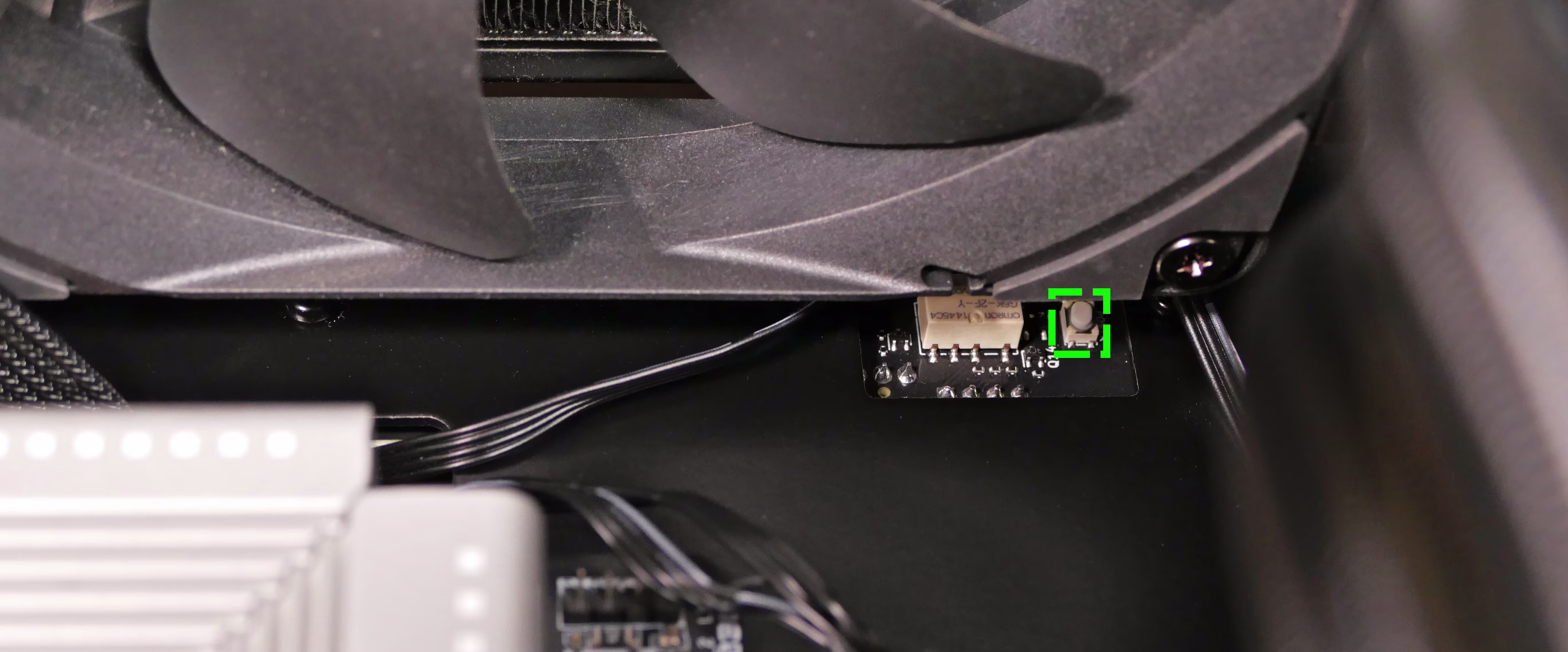
Steps to clear the CMOS:
Section titled “Steps to clear the CMOS:”- Follow the steps above to remove the left side panel.
- Push the top button, labeled
CLR_SW, near the CMOS battery (at the bottom right of the motherboard).- Do not confuse this button with the bottom button, labeled
RST_SW, which is near theCLR_CMOSjumper label.
- Do not confuse this button with the bottom button, labeled
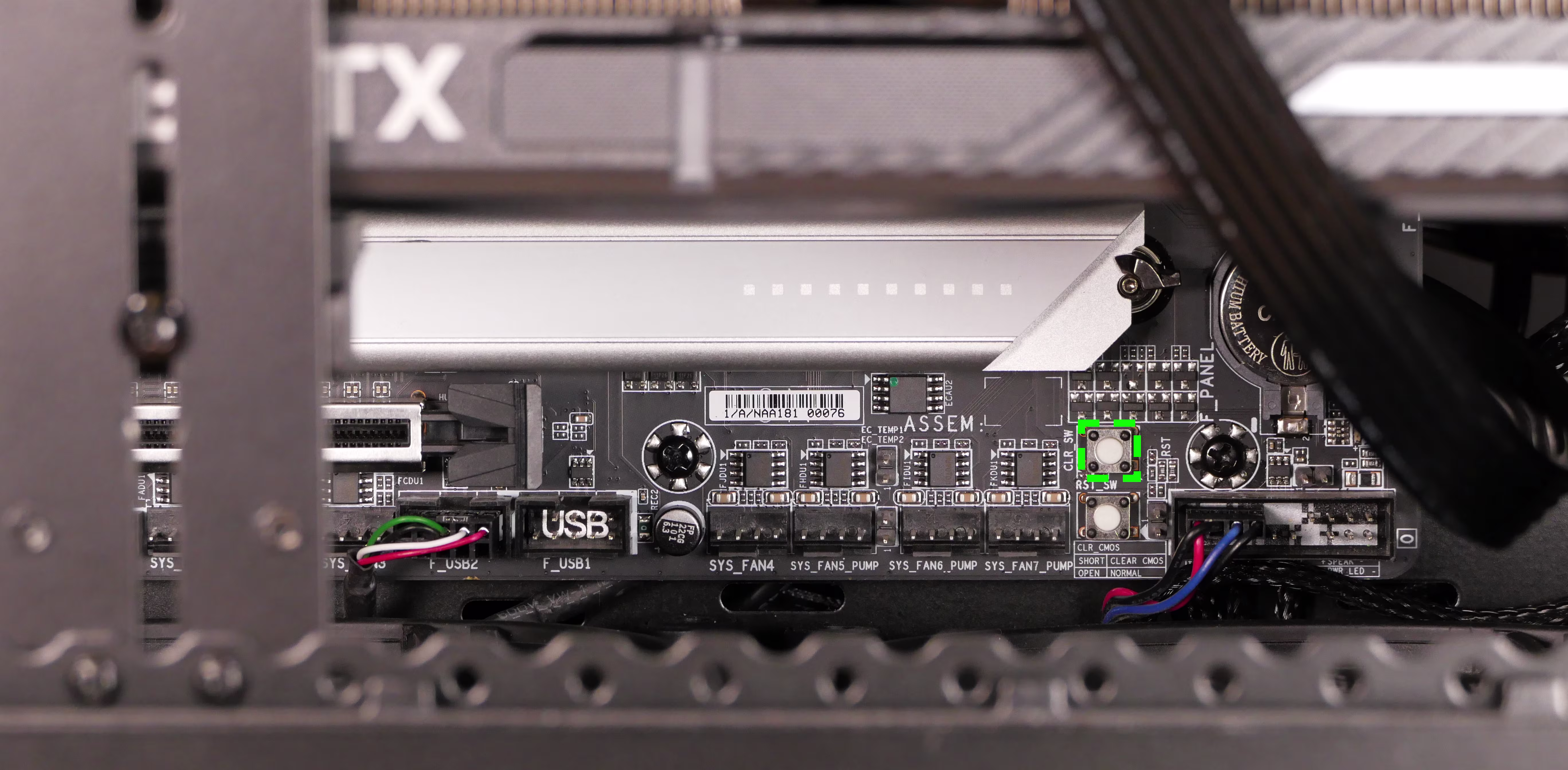
- Reinstall the left side panel.
Replacing the CMOS battery:
Section titled “Replacing the CMOS battery:”The CMOS battery supplies power to the system’s CMOS chip. UEFI settings and the computer’s hardware clock are stored on the CMOS. If your clock is constantly resetting, it’s likely your CMOS battery needs to be replaced. Removing the CMOS battery is also an alternative way to force a CMOS reset.
Warning (ingestion hazard): Keep batteries out of reach of children. Death or serious injury can occur if ingested. If a battery is suspected to be swallowed or inserted inside any part of the body, seek immediate medical attention. In the US, you can also call the National Battery Ingestion Hotline for guidance: +1 (800) 498-8666
Part numbers:
- The CMOS battery is a standard KTS CR2032 battery.
Tools required: Cross-head (Phillips) screwdriver, plastic flathead screwdriver
Time estimate: 20 minutes
Difficulty: Medium ●
Steps to replace the CMOS battery:
Section titled “Steps to replace the CMOS battery:”- Follow the steps above to remove the left side panel.
- Depending on the size of your GPU, you may also need to remove the front glass and remove the GPU brace and GPU.
- Lift the CMOS battery against the spring at the top of the slot by prying from behind the opening at the bottom of the slot.
- A flat plastic tool can be used to help lift the battery.
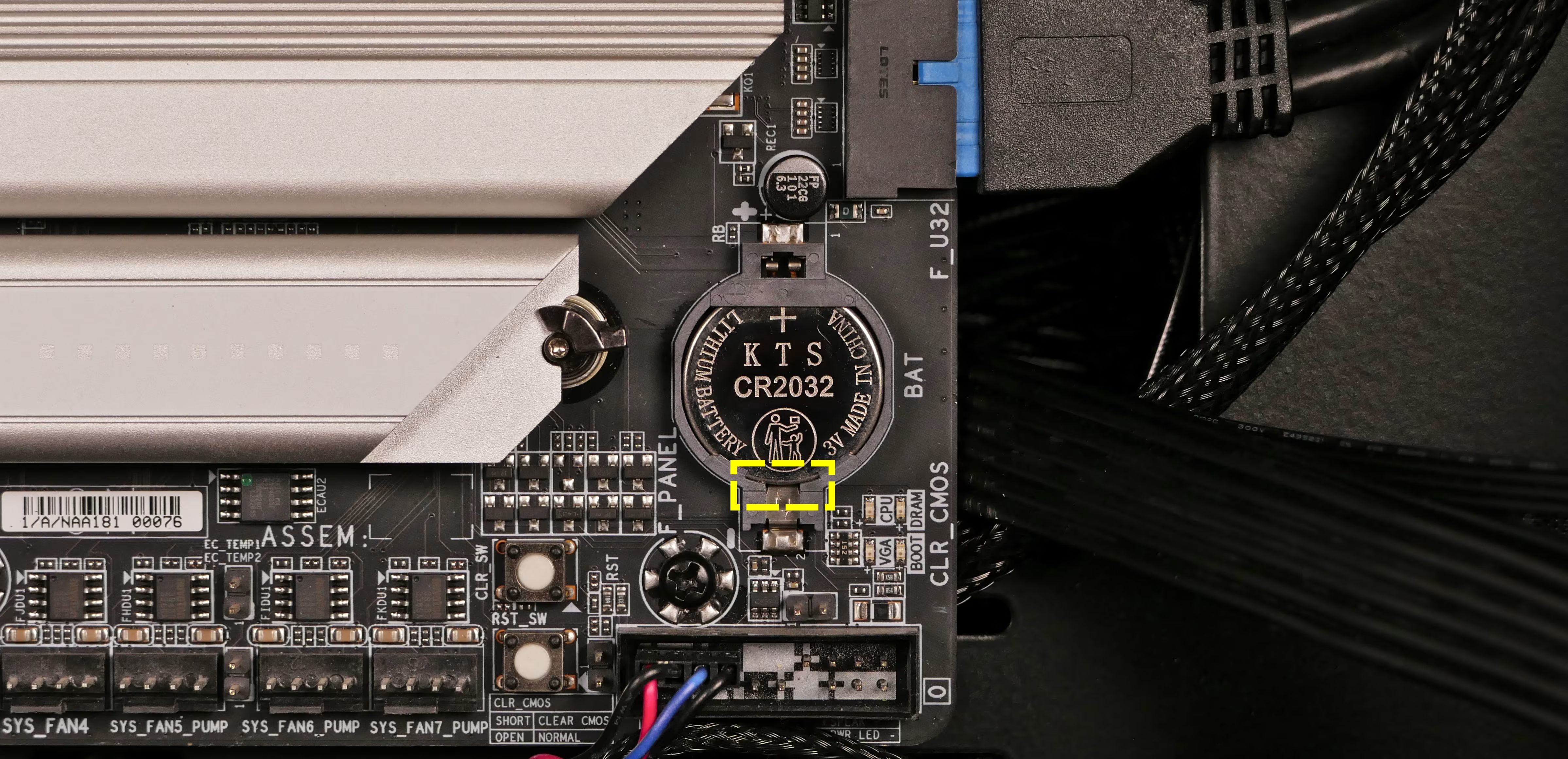
- Pull the CMOS battery out of its slot.
- If you are resetting the CMOS, hold down the power button for 10 seconds to discharge any residual energy in the system.
- Install the new CMOS battery (or reinstall the existing CMOS battery) starting at the top of the slot.
- The positive side of the battery (with text) should face outward.
- Replace the GPU, GPU brace, front glass, and left side panel as applicable.
Accessing spare 2.5“ drive screws:
Section titled “Accessing spare 2.5“ drive screws:”Additional screws for 2.5“ storage drives are stored under the top shell of the machine.
Tools required: Cross-head (Phillips) screwdriver (optional)
Time estimate: 7 minutes
Difficulty: Easy ●
Steps to access spare 2.5“ drive screws:
Section titled “Steps to access spare 2.5“ drive screws:”- Follow the steps above to remove the left and right side panels, remove the front glass, and remove the top shell.
- Pop the plastic ring out of the diagonal crossbar.
- Slide four screws (per drive) out of the crossbar’s cutout.
- Reinstall the plastic ring, top shell, front glass, and left side panel.
Adding/removing 2.5“ storage drives:
Section titled “Adding/removing 2.5“ storage drives:”Thelio Major R5-N4 supports up to two SATA III drives per drive cage.
- For single-PSU configurations, the included 2.5“ drive cage is preinstalled in the back of the chassis.
- For dual-PSU configurations, the included 2.5“ drive cage is preinstalled in the front of the chassis.
Tools required: Cross-head (Phillips) screwdriver
Time estimate: 7 minutes
Difficulty: Easy ●
Steps to add/remove 2.5“ storage drives (back cage):
Section titled “Steps to add/remove 2.5“ storage drives (back cage):”- Unscrew the backplate labeled
2.5" DRIVES.
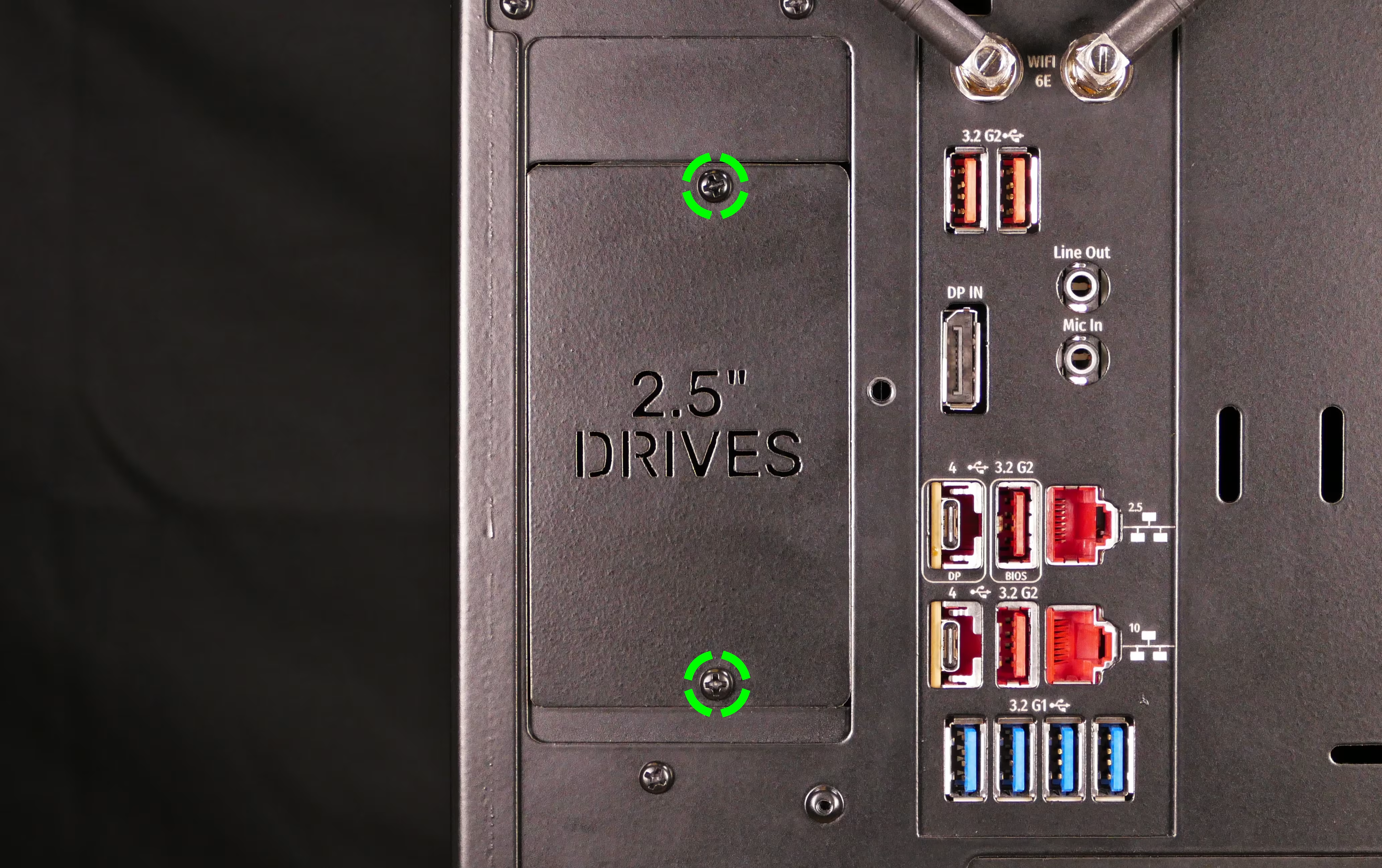
- If screws for your drive aren’t already installed in the 2.5“ drive cage, follow the steps above to remove the side panels, remove the front glass, remove the top shell, and access the spare 2.5“ drive screws.
- Insert four screws into each 2.5“ storage drive you wish to install.
- Slide each 2.5“ drive into one of the slots leading to the SATA backplane.
- The larger group of pins goes on the top.
- Replace the 2.5“ drive bay cover.
Steps to add/remove 2.5“ storage drives (front cage):
Section titled “Steps to add/remove 2.5“ storage drives (front cage):”- Follow the steps above to remove the left side panel.
- Unscrew the cover labeled
2.5" DRIVES.
- If screws for your drive aren’t already installed in the 2.5“ drive cage, follow the steps above to remove the right side panel, remove the front glass, remove the top shell, and access the spare 2.5“ drive screws.
- Insert four screws into each 2.5“ storage drive you wish to install.
- Slide each 2.5“ drive into one of the slots leading to the SATA backplane.
- The larger group of pins goes on the top.
- Replace the 2.5“ drive bay cover.
Installing a front 2.5“ or 3.5“ drive cage:
Section titled “Installing a front 2.5“ or 3.5“ drive cage:”- Single-PSU configurations, which include a single 2.5“ drive cage installed in the back of the chassis, can have an additional 2.5“ or 3.5“ drive cage (purchased separately) installed in the front of the chassis.
- Single-PSU configurations support up to four 2.5“ drives, or two 2.5“ and two 3.5“ drives.
- Dual-PSU configurations have the included 2.5“ drive cage preinstalled in the front of the chassis, which can be swapped out with a 3.5“ drive cage (purchased separately).
- Dual-PSU configurations support up to two 2.5“ drives or two 3.5“ drives.
- If you’re installing a 3.5“ drive cage in a dual-PSU configuration, reference the 2.5“ drive cage installation steps to remove the 2.5“ drive cage first.
Tools required: Cross-head (Phillips) screwdriver
Time estimate: 15 minutes
Difficulty: Easy ●
Steps to install a front 2.5“ drive cage:
Section titled “Steps to install a front 2.5“ drive cage:”- Follow the steps above to remove both side panels and remove the front glass; also remove the new 2.5“ drive cage’s cover (if installed).
- If it’s not already installed, insert the 2.5“ drive backplane into the 2.5“ drive cage, then screw it in from the back.
- On the interior of the cage, the backplane’s larger side gap should face towards the closed side of the cage.
- On the exterior of the cage, the orientation of the backplane will cause the port labels to be upside-down when the cage is installed in the Thelio.
- Screw the 2.5“ drive cage onto the front of the chassis.
- Connect the backplane to any two available SATA ports on the motherboard, and to the power supply.
- Four of the SATA ports (labeled
SATA3) are located behind the dedicated GPU, but can be accessed from behind using the cutout behind the right side panel. By default, the top two ports of this section (0and1) are connected to the included 2.5“ bay. - The other four SATA ports (labeled
A_SATA3) are located above the dedicated GPU.
- Four of the SATA ports (labeled
- If drive mounting screws weren’t included with the additional 2.5“ cage, remove the top shell to access the extra screws.
- Install any desired drives in the 2.5“ cage, followed by the cage’s cover.
Steps to install a front 3.5“ drive cage:
Section titled “Steps to install a front 3.5“ drive cage:”- Follow the steps above to remove both side panels and remove the front glass.
- While holding the 3.5“ drive cage in place (against the liquid cooler hoses), screw it onto the front of the chassis.
- If drive mounting screws weren’t included with the 3.5“ cage, remove the top shell to access the extra screws.
- Install any desired drives in the 3.5“ cage.
- The drives should be oriented so the larger portion faces the front of the chassis.
- After installing any desired drives in the 3.5“ cage, install the 3.5“ cage’s cover.
- Connect any installed 3.5“ drives to any available SATA ports on the motherboard, and to the power supply.
- Four of the SATA ports (labeled
SATA3) are located behind the dedicated GPU, but can be accessed from behind using the cutout behind the right side panel. By default, the top two ports of this section (0and1) are connected to the included 2.5“ bay. - The other four SATA ports (labeled
A_SATA3) are located above the dedicated GPU.
- Four of the SATA ports (labeled
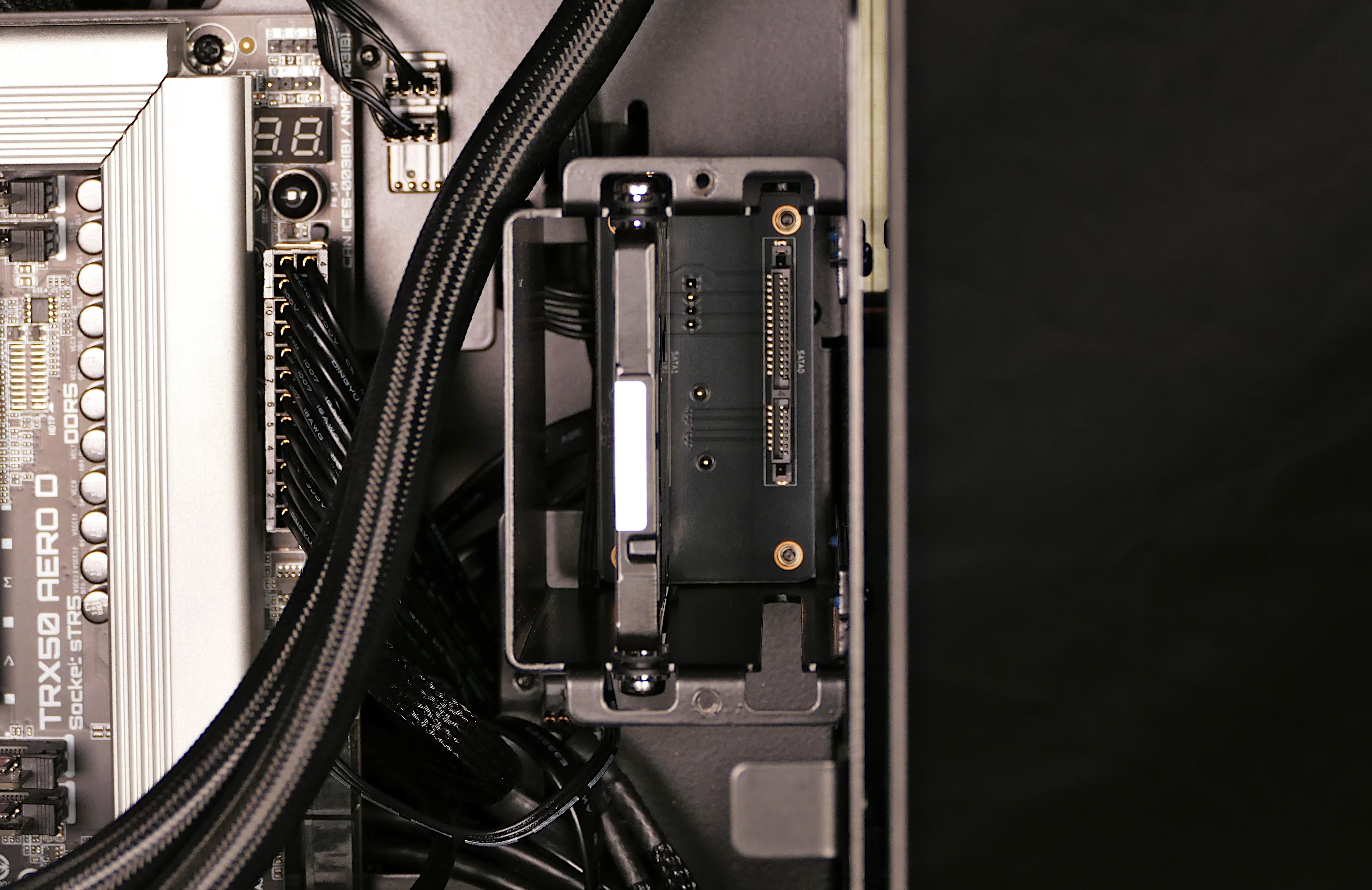
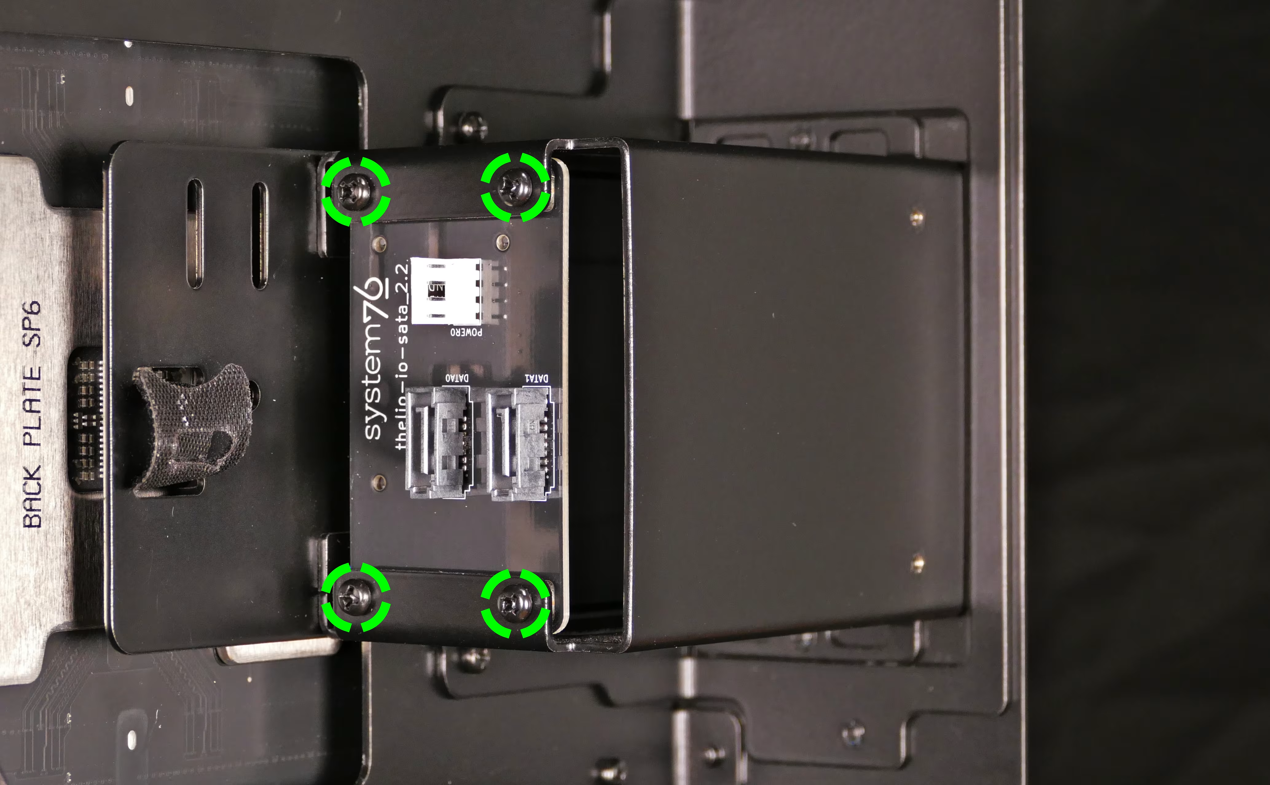
Replacing the included 2.5“ backplane:
Section titled “Replacing the included 2.5“ backplane:”The backplane that connects 2.5“ storage drives to the system upon insertion can be independently replaced using the steps below.
Tools required: Cross-head (Phillips) screwdriver
Time estimate: 15 minutes
Difficulty: Easy ●
Steps to replace the 2.5“ backplane (back cage):
Section titled “Steps to replace the 2.5“ backplane (back cage):”- Follow the steps above to remove the 2.5“ backplate and any installed 2.5“ storage drives and remove the right side panel.
- Unplug the SATA and power connectors from the back of the 2.5“ backplane.
- Unscrew the four screws holding the 2.5“ backplane into the 2.5“ bay.
- Remove the old backplane from the 2.5“ bay by tilting it until it fits out the back of the bay.
- Alternatively, push the backplane out the back of the computer.
- Insert the new backplane into the 2.5“ bay.
- The backplane should be oriented so the port labels are upside-down.
- Screw the new backplane into the 2.5“ bay.
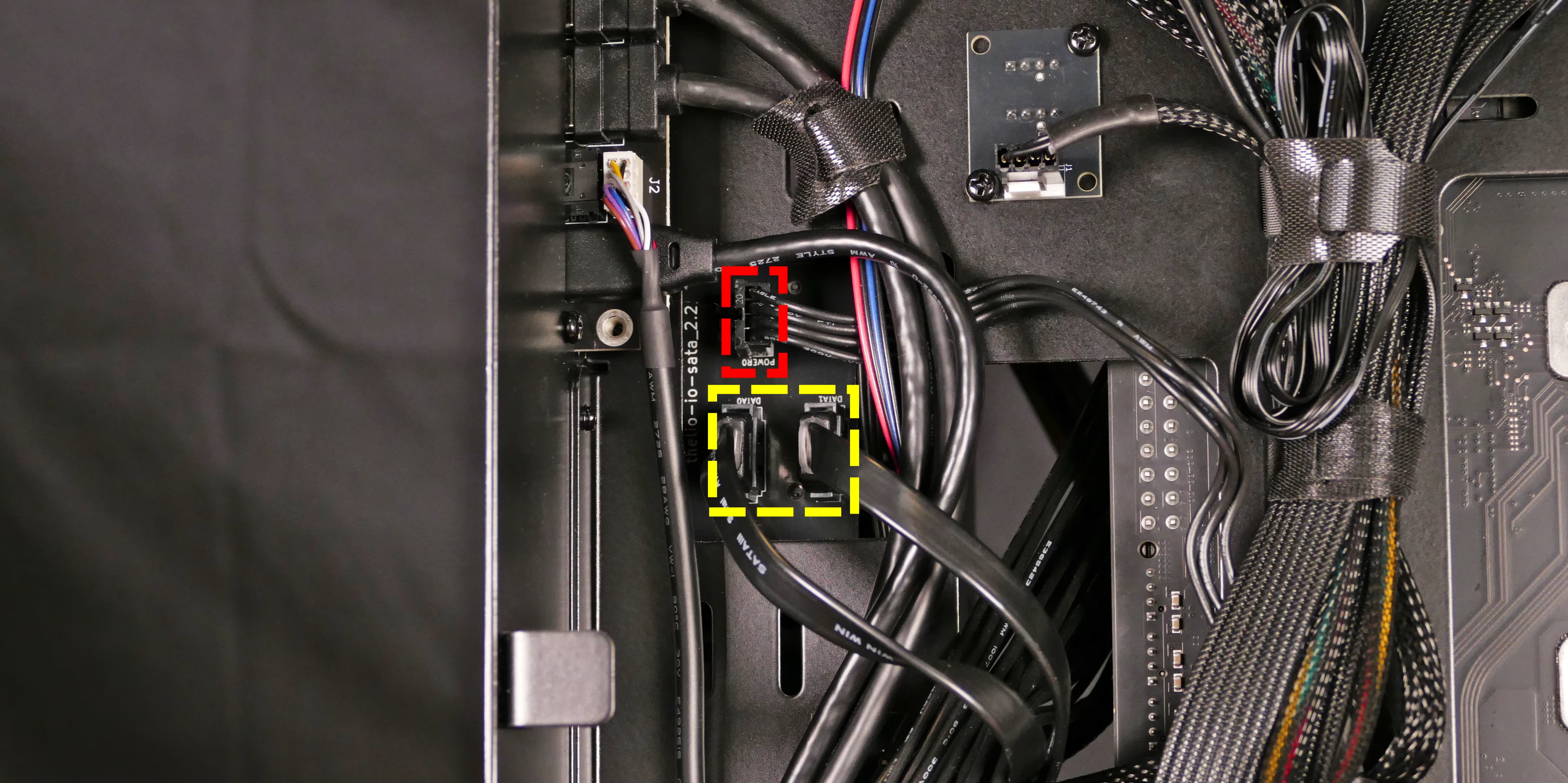
- Plug the SATA and power connectors into the new backplane.
- The order of the SATA data cables shouldn’t matter as long as your operating system and software is configured to address disks by UUID (e.g.
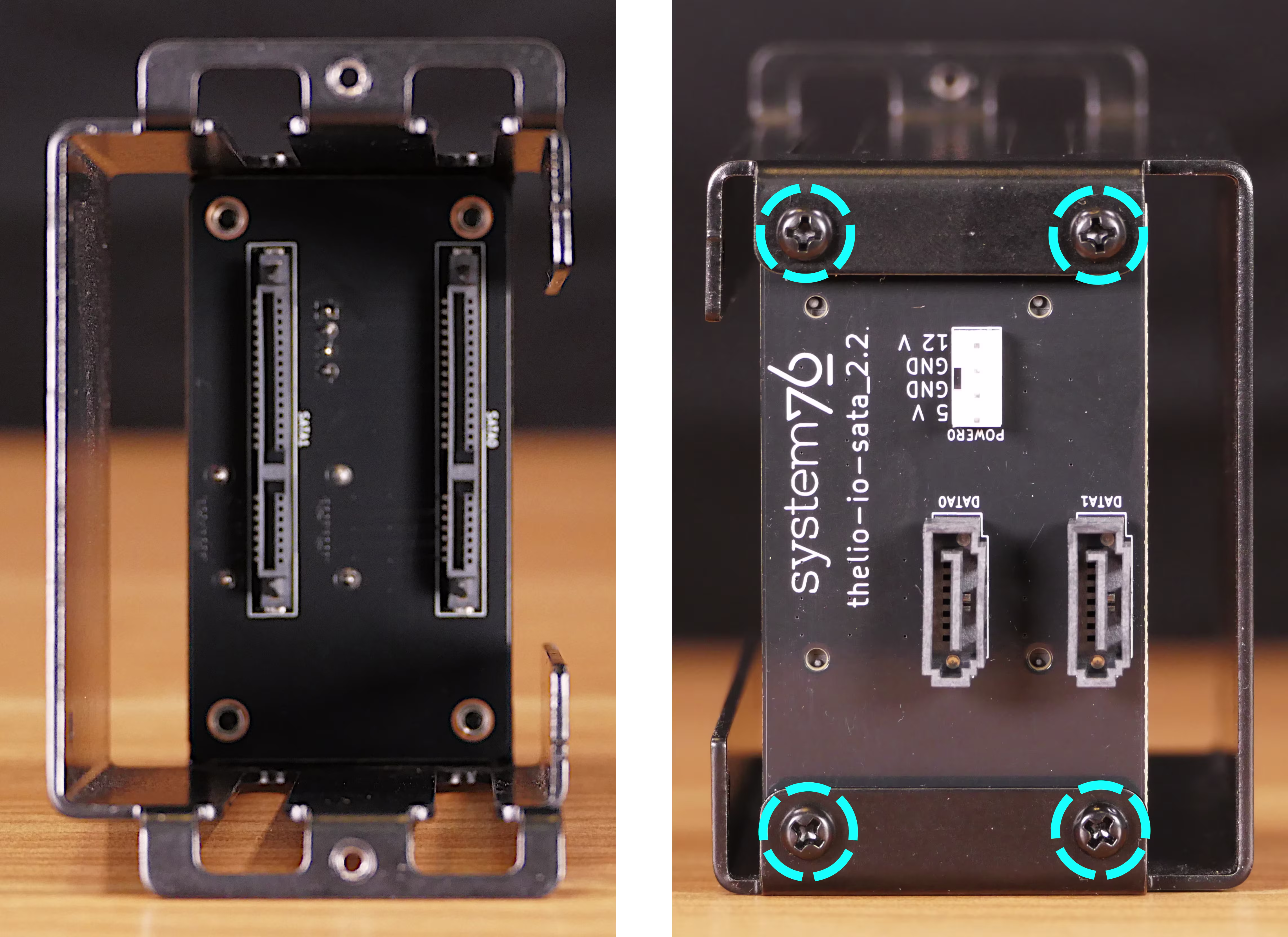
/dev/disk/by-uuid/...) instead of by letter (e.g./dev/sd_). - By default, the ports connect as follows:
DATA0(on the left) connects toSATA3port0(on the left, farthest from the motherboard).DATA1(on the right) connects toSATA3port1(on the right, closest to the motherboard).POWERuses a 4-pin Berg adapter, which connects to a SATA power cable leading to the power supply.
- The order of the SATA data cables shouldn’t matter as long as your operating system and software is configured to address disks by UUID (e.g.
Steps to replace the 2.5“ backplane (front cage):
Section titled “Steps to replace the 2.5“ backplane (front cage):”- Follow the steps above to remove the side panels, then remove the 2.5“ cover and any installed 2.5“ storage drives.
- Unplug the SATA and power connectors from the back of the 2.5“ backplane.
- Remove the front 2.5“ cage, remove the old backplane, install the new backplane, then reinstall the cage.
- Plug the SATA and power connectors into the new backplane.
- The order of the SATA data cables shouldn’t matter as long as your operating system and software is configured to address disks by UUID (e.g.
/dev/disk/by-uuid/...) instead of by letter (e.g./dev/sd_). - By default, the ports connect as follows:
DATA0(on the left) connects toSATA3port0(on the left, farthest from the motherboard).DATA1(on the right) connects toSATA3port1(on the right, closest to the motherboard).POWERuses a 4-pin Berg adapter, which connects to a SATA power cable leading to the power supply.
- The order of the SATA data cables shouldn’t matter as long as your operating system and software is configured to address disks by UUID (e.g.
Replacing a power supply:
Section titled “Replacing a power supply:”Thelio Major R5-N4 uses one 1000W or two 750W SFX (small form-factor) power supplies.
Part numbers:
- 1000W models:
- Thermaltake
PS-STP-1000FNFAPU-1 - Lian Li
SP1000P.B - …or other equivalent
- Thermaltake
- 750W model: Lian Li
SP750G.B(or equivalent)
Tools required: Cross-head (Phillips) screwdriver
Time estimate: 45 minutes
Difficulty: Medium ●
Steps to replace a power supply:
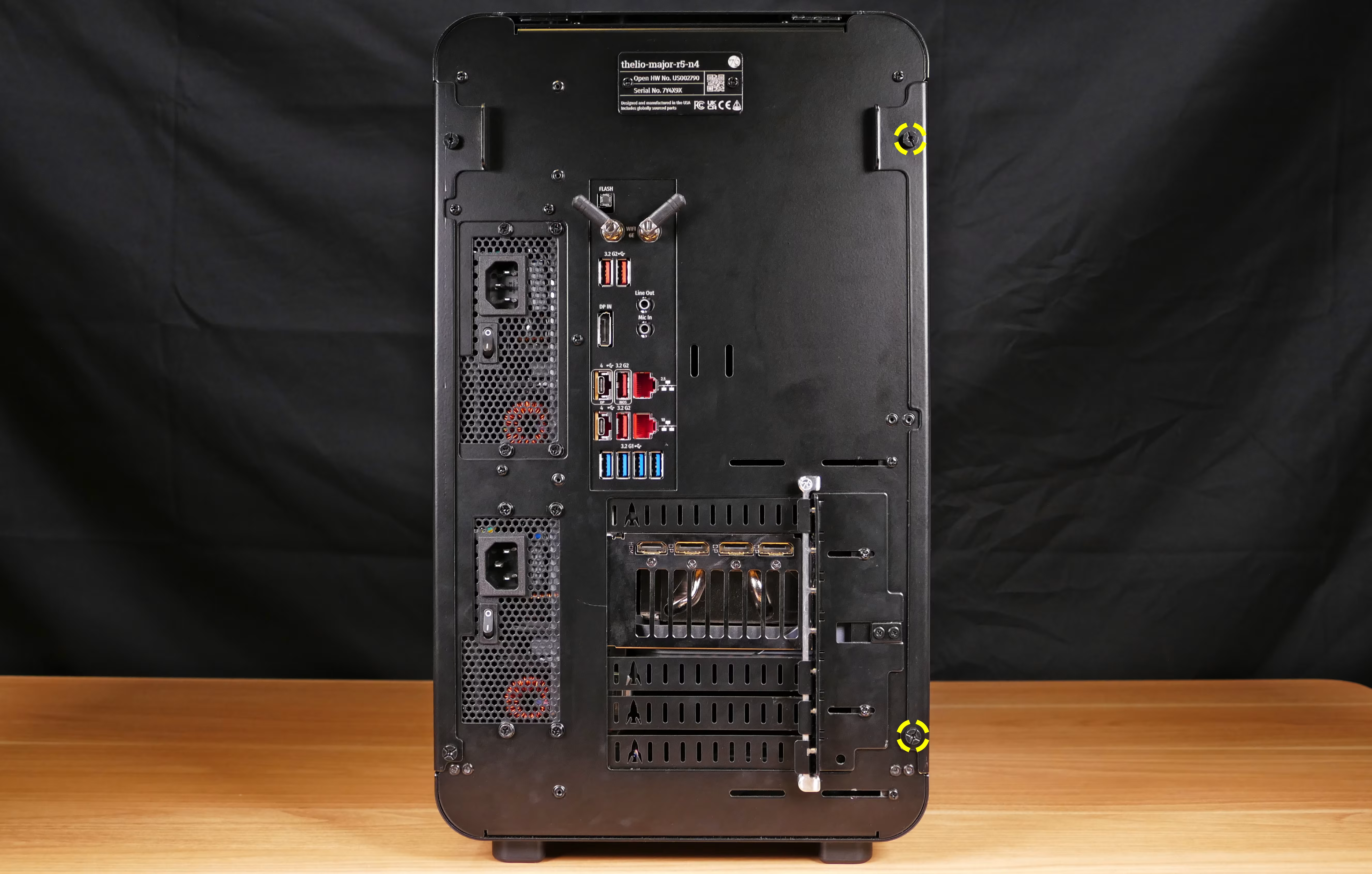
Section titled “Steps to replace a power supply:”- Follow the steps above to remove the right side panel.
- Unscrew the power supply’s four screws from the back of the chassis.
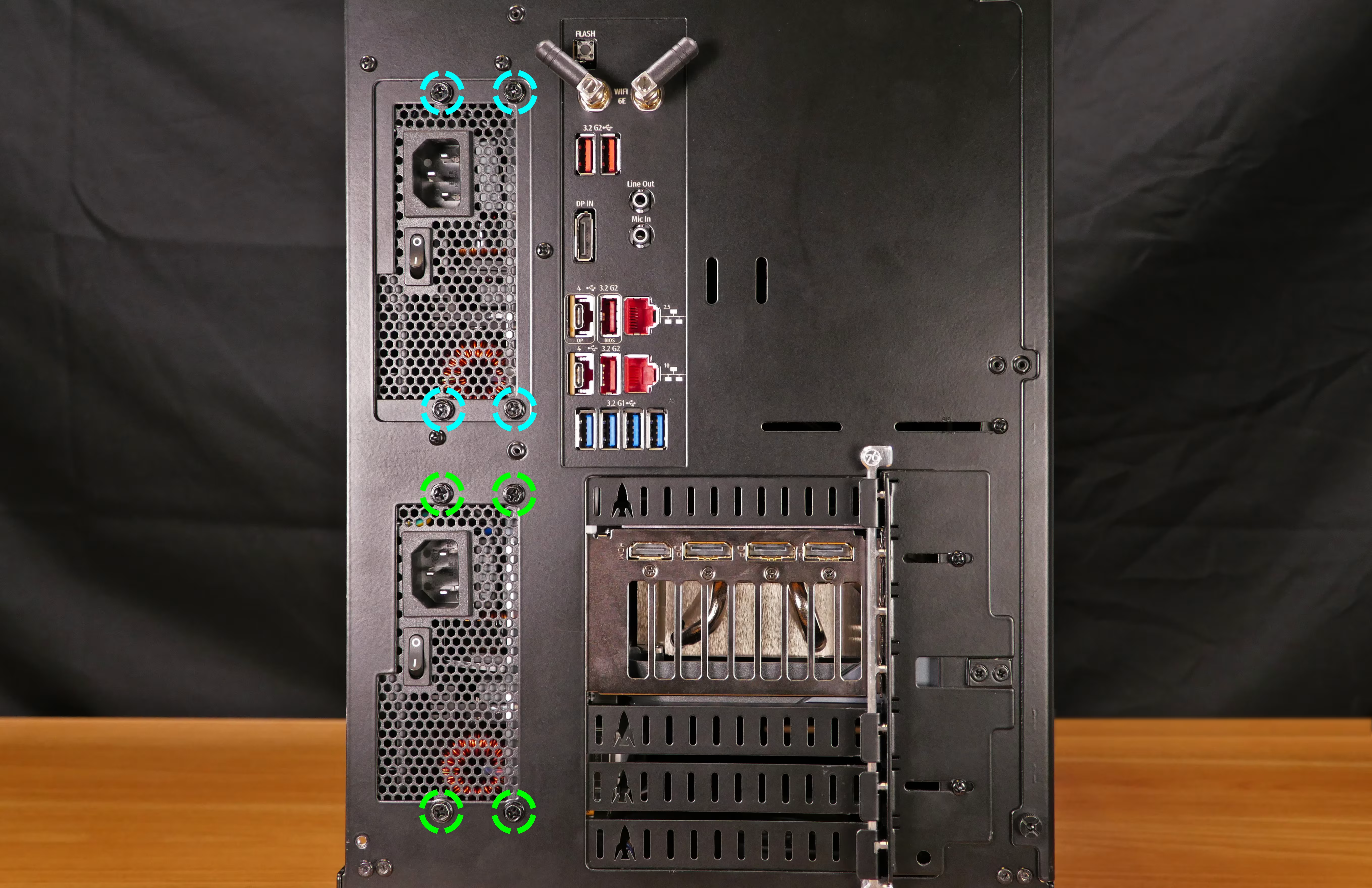
- Unplug all of the modular cabling from the back of the PSU.
- If you’re replacing both PSUs, replace them one at a time, or mark which cables connect to which PSU before disconnecting them.
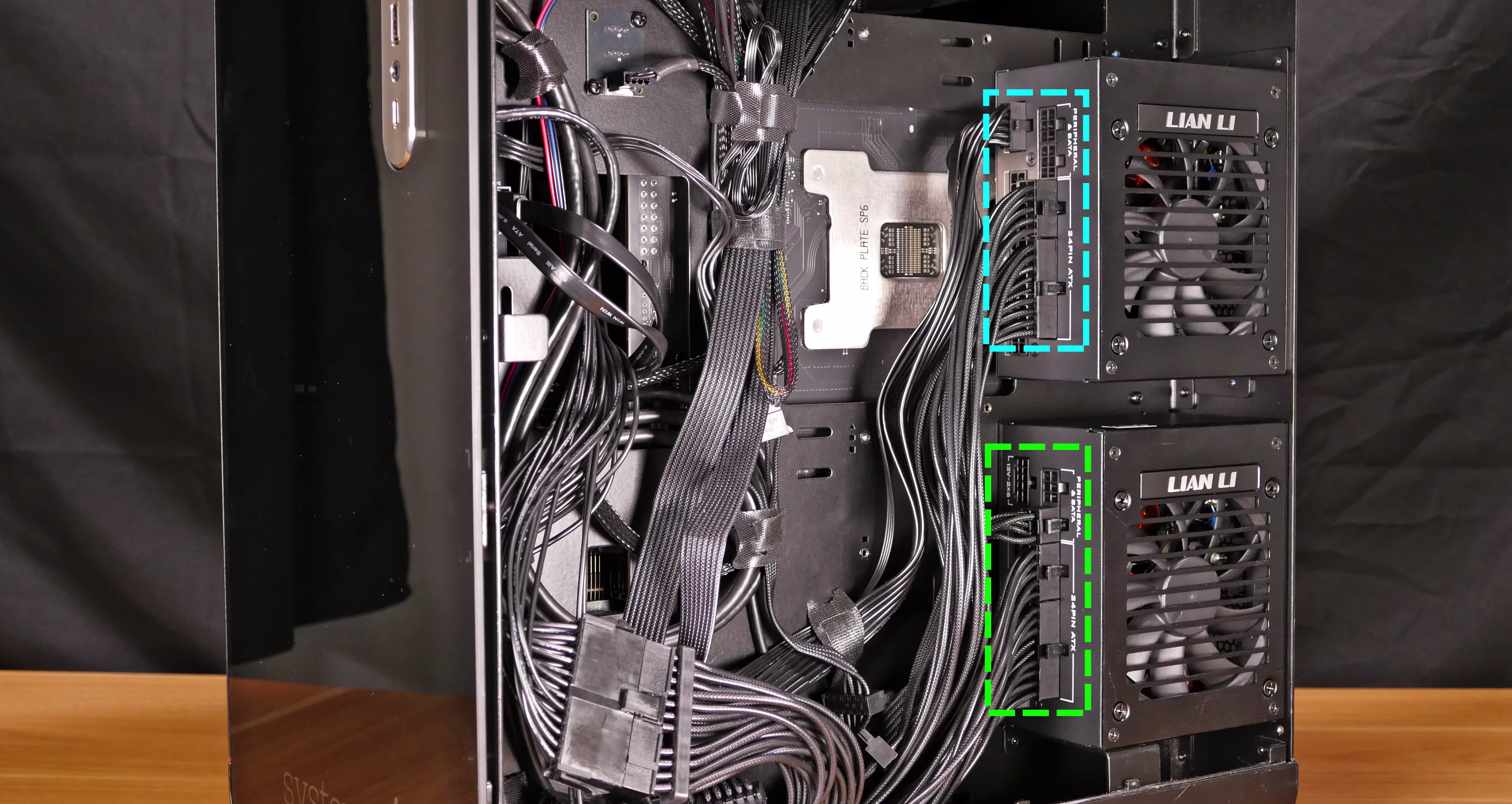
- Remove/replace the power supply.
- The replacement PSU should be installed with the fan facing out of the case.
- Hold the PSU against the screwholes in the back of the case while attaching it.
- Connect the power cables to the new power supply.
- If the new PSU is not the same model as the old one, it’s recommended to completely remove the old power cables and replace them with the cables that came with the new PSU.
- Reinstall the right side panel.
Cleaning the side dust filters:
Section titled “Cleaning the side dust filters:”The side intake fans are covered by individual dust filters, which can be removed for cleaning.
Tools required: Cross-head (Phillips) screwdriver
Time estimate: 10 minutes
Difficulty: Easy ●
Steps to clean the side dust filters:
Section titled “Steps to clean the side dust filters:”- Follow the steps above to remove the left side panel.
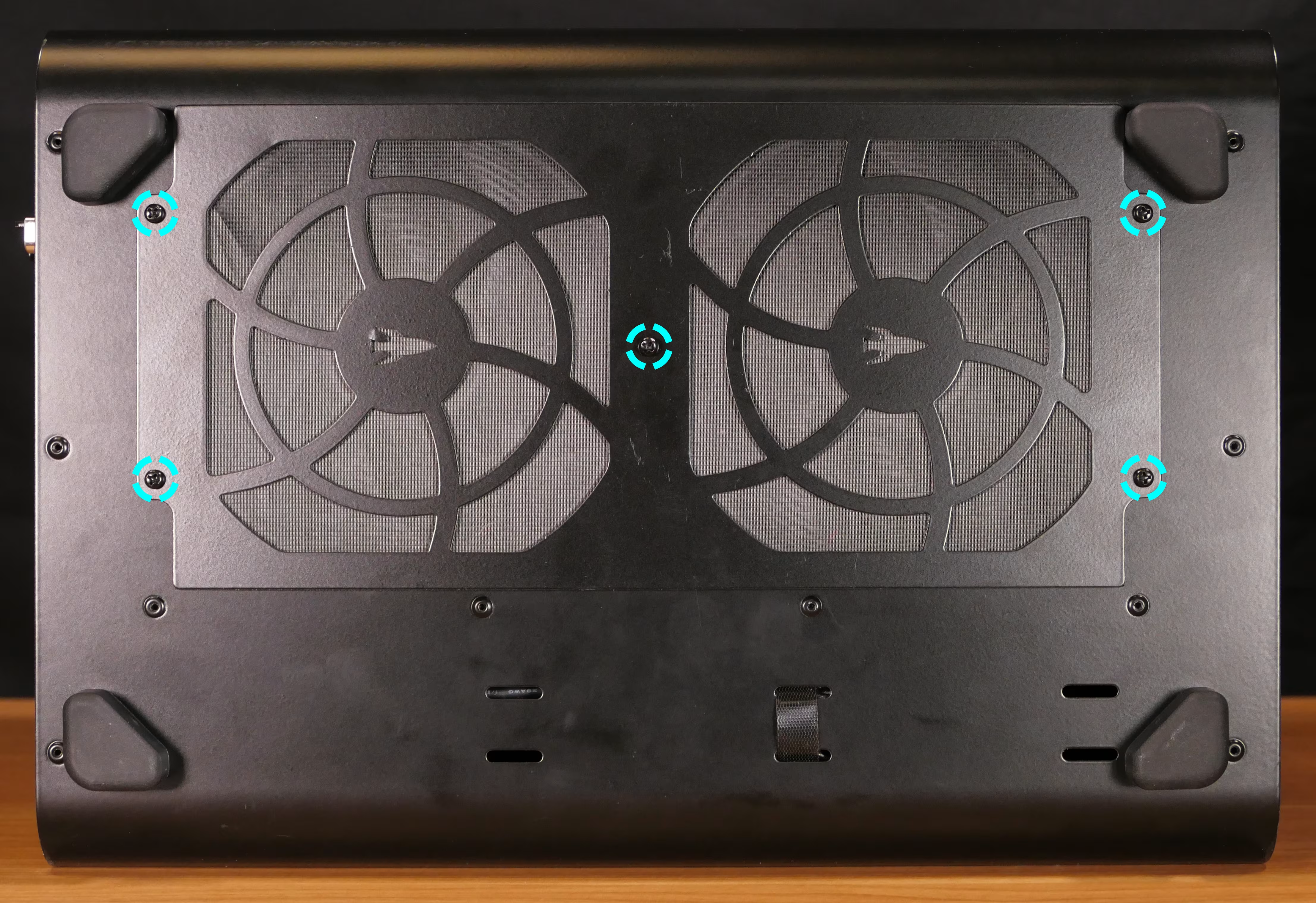
- Unscrew the four screws holding the fan panel onto the side panel.
- Do not unscrew any of the six sideways screws.
- Unscrew the four screws (per fan) holding the dust filter and fan onto the panel.
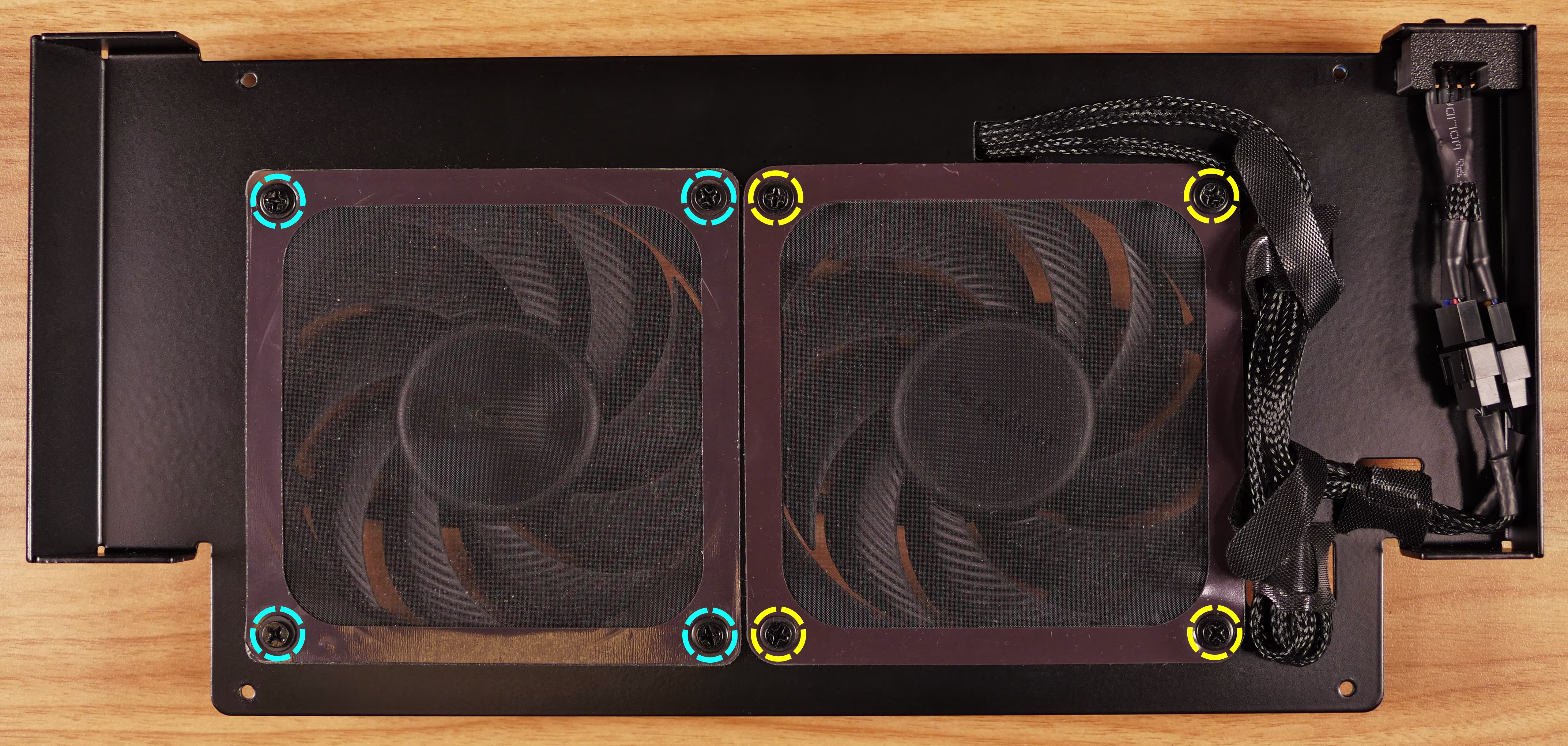
- Pull the dust filters off of the panel.
- If you’re not replacing the fans, leave them in place under the panel to keep them in the correct orientation.
- Clean dust out of the dust filter using compressed air or gentle running water.
- If liquid is used to clean the dust filter, wait until the dust filter has completely dried before reinstalling it.
- Reinstall each dust filter.
- The glossy side of the dust filter should face away from the panel; the matte side should face towards the panel.
- The curved/glossy side of the washer faces the screw head; the flat/matte side faces the dust filter.
- From bottom to top, the order of components should be: fan, panel, dust filter, washer, screw.
- Reattach the fan panel to the rest of the left side panel.
- The pogo pins should be visible and nearest to the top of the panel.
- Reinstall the left side panel.
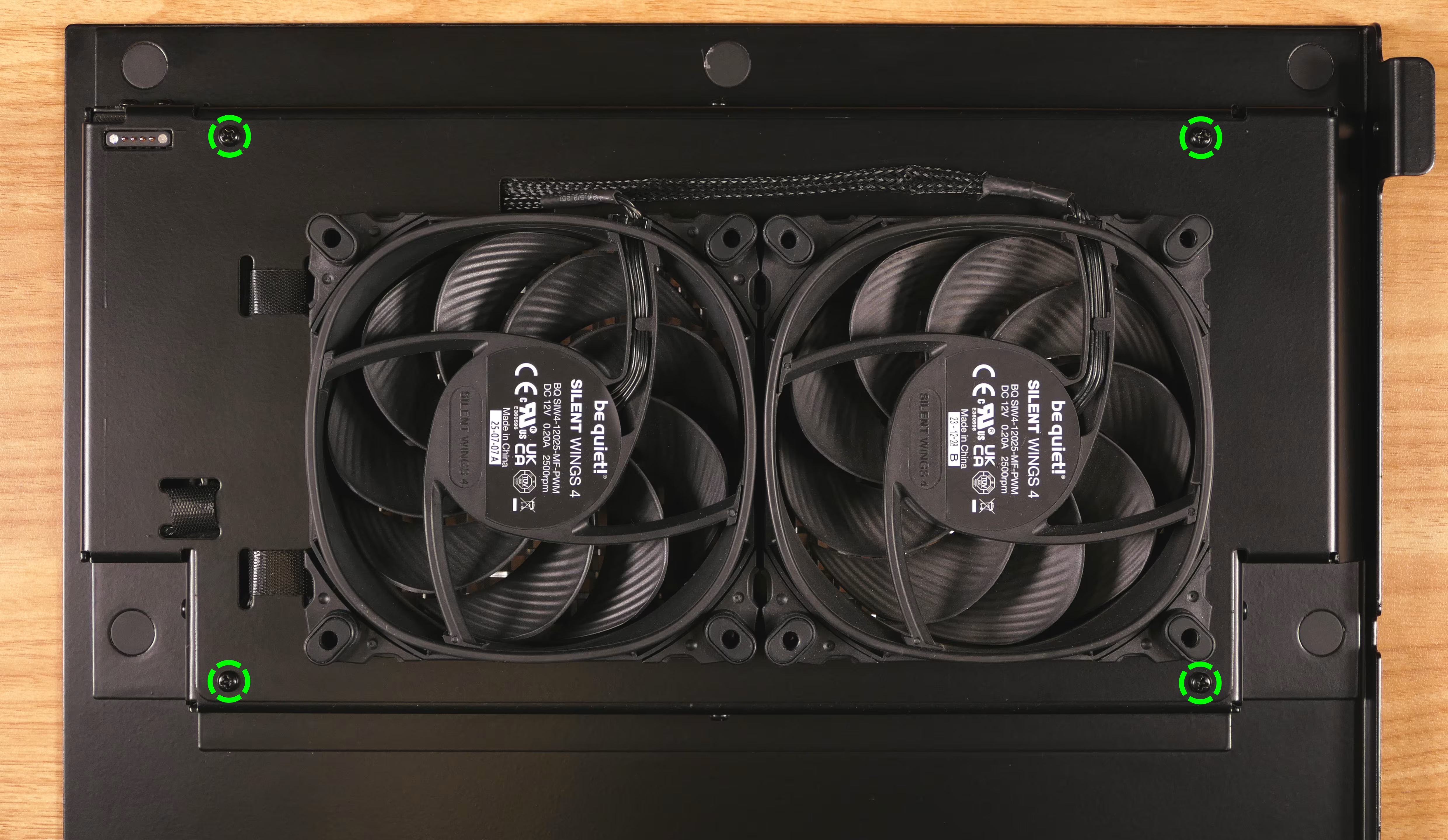
Replacing the side fans:
Section titled “Replacing the side fans:”The two 120mm side intake fans can be individually replaced.
Part numbers:
- Side fans: Be Quiet! Silent Wings 4 120mm (
SIW4-12025-MF-PWM)
Tools required: Cross-head (Phillips) screwdriver
Time estimate: 25 minutes
Difficulty: Easy ●
Steps to replace the side fans:
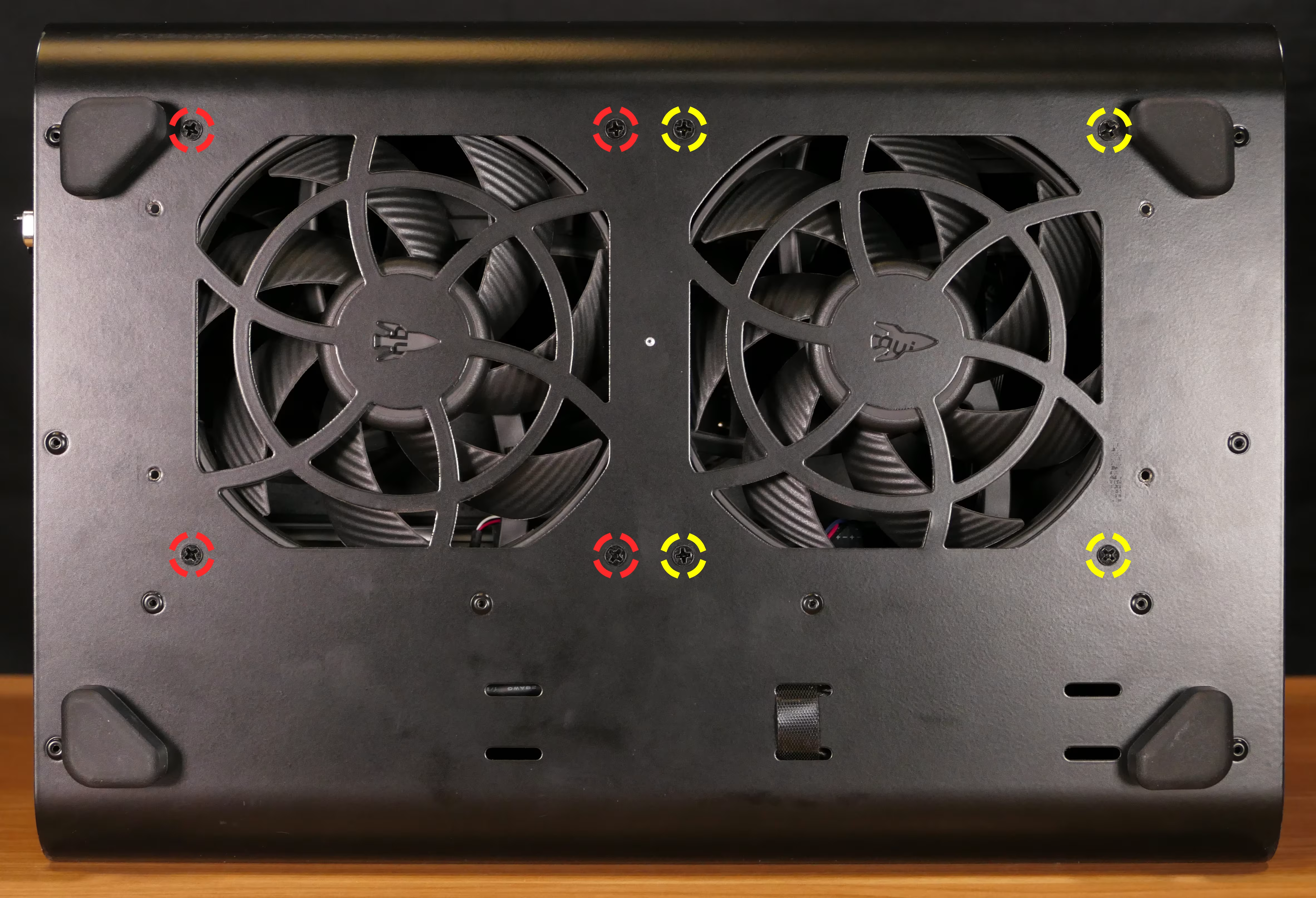
Section titled “Steps to replace the side fans:”- Follow the steps above to remove the left side panel and remove the side fan dust filters and screws.
- Disconnect then fan(s) being replaced from the pogo pin fan splitter.
- By default, the fan pictured on the left is plugged into the left connector of the splitter, and the fan pictured on the right is plugged into the right connector. However, both connectors provide the same signal.
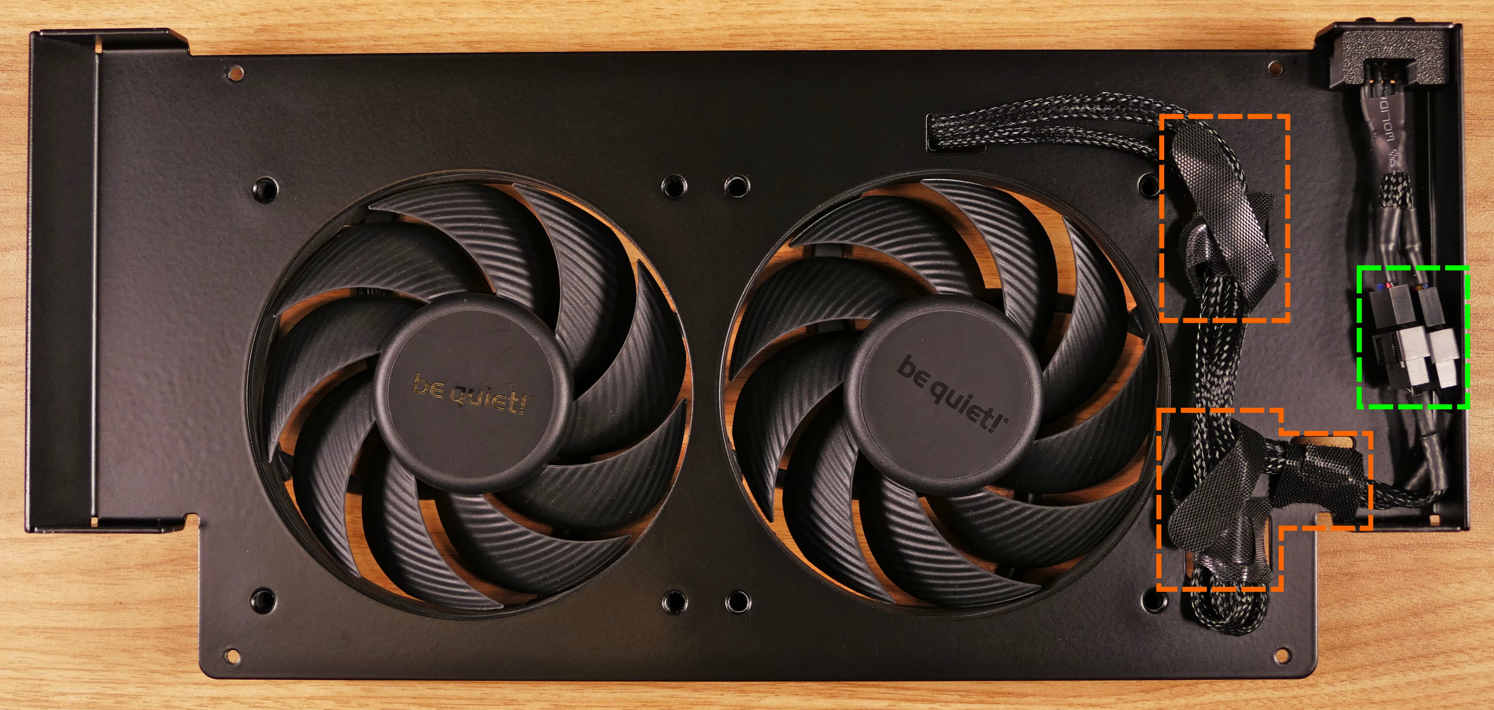
- Unfasten the velcro strips and free the fan cables.
- Pull each fan being replaced away from the panel, passing the end of the cable through the channel in the panel.
- Place the new fan(s) under the panel.
- With the panel oriented as shown above, both fans should be oriented so their cables point towards the top left.
- The spinning side of the fan should face through the panel, while the stationary cover should face away from the panel.
- Screw each fan into the panel along with its corresponding dust filter.
- The glossy side of the dust filter should face away from the panel; the matte side should face towards the panel.
- The curved/glossy side of the washer faces the screw head; the flat/matte side faces the dust filter.
- From bottom to top, the order of components should be: fan, panel, dust filter, washer, screw.
- Reattach the fan panel to the rest of the left side panel.
- The pogo pins should be visible and nearest to the top of the panel.
- Reinstall the left side panel.
Cleaning the bottom dust filter:
Section titled “Cleaning the bottom dust filter:”The bottom intake fans are covered by a dust filter, which can be removed for cleaning.
Tools required: Cross-head (Phillips) screwdriver
Time estimate: 5 minutes
Difficulty: Easy ●
Steps to clean the bottom dust filter:
Section titled “Steps to clean the bottom dust filter:”- Lay the machine down on its right side, with the mesh window facing upwards.
- Use a soft surface (such as a towel) to avoid scratching the chassis.
- Unscrew the five screws holding the dust filter onto the machine.
- Pull the dust filter off of the machine.
- Clean dust out of the dust filter using compressed air or gentle running water.
- If liquid is used to clean the dust filter, wait until the dust filter has completely dried before reinstalling it.
- While holding the dust filter onto the bottom of the machine, reinstall its five screws.
- By default, the rockets point towards the front of the machine.
- The mesh should face inward towards the chassis, with the metal frame facing outward.
Replacing the bottom fans:
Section titled “Replacing the bottom fans:”The two 140mm bottom intake fans can be individually replaced.
Part numbers:
- Bottom fans: Be Quiet! Silent Wings 4 140mm (
SIW4-14025-MF-PWM)
Tools required: Cross-head (Phillips) screwdriver
Time estimate: 20 minutes
Difficulty: Easy ●
Steps to replace the bottom fans:
Section titled “Steps to replace the bottom fans:”- Follow the steps above to remove the left side panel.
- Unplug the fan(s) being replaced from the bottom fan splitter.
- Turn the machine on its right side and remove the bottom dust filter.
- Remove the four screws (per fan) securing the fan to the chassis.
- Screw in the new fan(s).
- Reinstall the bottom dust filter.
- Set the machine upright again and plug the new fan(s) into the bottom fan splitter.
- Reinstall the left side panel.
Replacing the CPU cooler and CPU:
Section titled “Replacing the CPU cooler and CPU:”Thelio Major R5-N4 includes a self-contained liquid cooler to dissipate heat from the CPU to the radiator, where the CPU cooler’s fans expel it from the system. Supported cooler sizes are 280mm (2x140mm) and 240mm (2x120mm). Depending on your climate and the age of the machine, replacing the thermal paste between the CPU and the cooler may help lower operating temperatures.
Part numbers:
- CPU cooler (280mm or 240mm):
- Apaltek DW0149 TR5 280mm AIO Cooler
- …or equivalent.
- The CPU uses an AMD AM5 socket.
Tools required: Cross-head (Phillips) screwdriver, AMD Threadripper torque tool or compatible 1.5 Nm (13.275 in-lb) torque 3.95mm six-point star (Torx T20) screwdriver, thermal paste
Time estimate: 45 minutes
Difficulty: High ●
Steps to remove the CPU cooler/thermal paste:
Section titled “Steps to remove the CPU cooler/thermal paste:”- Follow the steps above to remove the left and right side panels, remove the front glass, and remove the top shell.
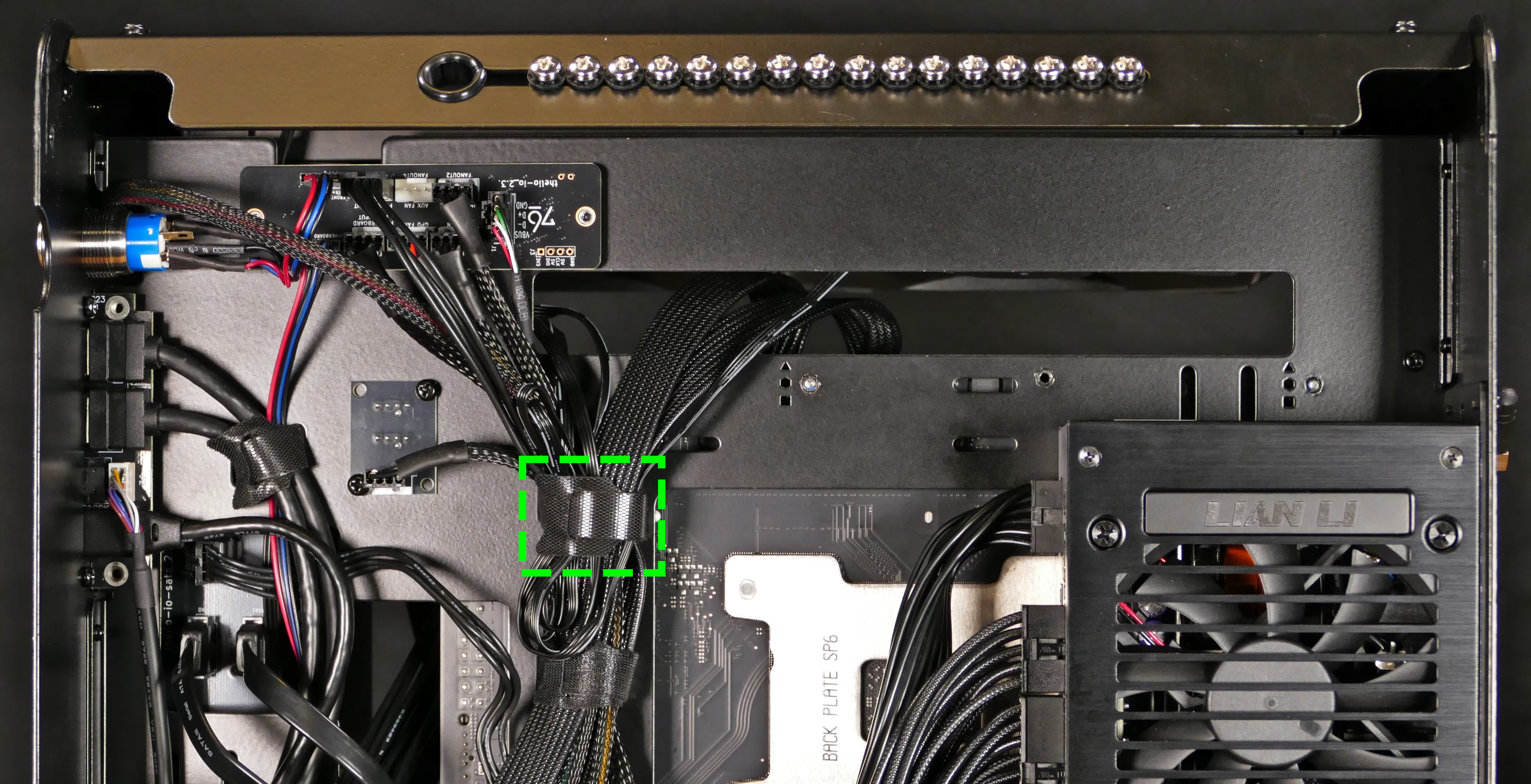
- Unfasten the velcro strip(s) to free any signal cables leading to the CPU cooler or its fans.
- The four-wire fan cables are secured in the velcro before extending back out to the dual-port splitter next to the motherboard.
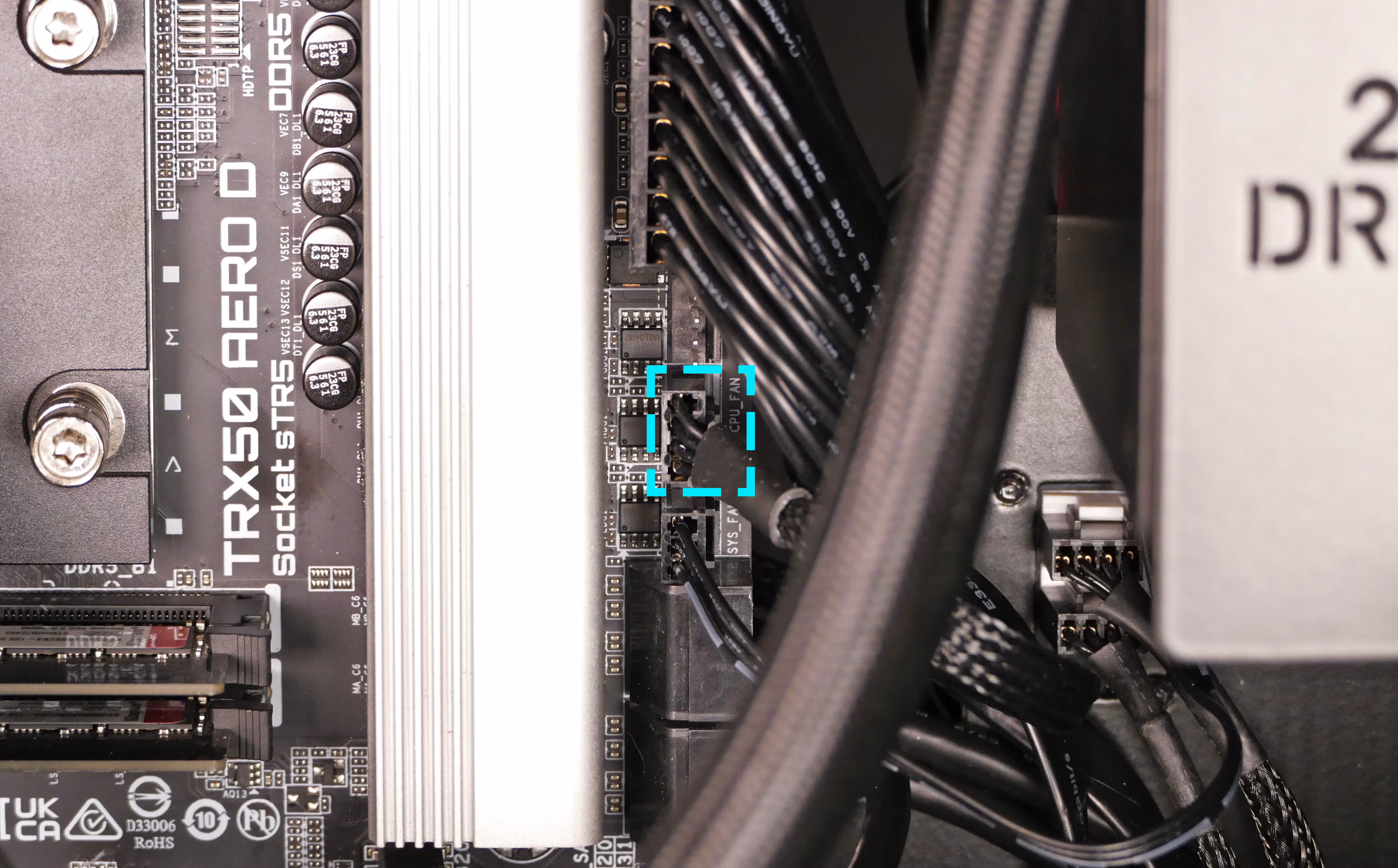
- The three-wire cable extending from the top of the radiator plugs into the motherboard’s
SYS_FAN8_PUMPheader.- This cable does not need to be tied back due to its short length.
- The braided cable leading to the
FANIN1port of the Thelio Io board plugs into the motherboard’sCPU_FAN1header. Another braided cable connects the back of the dual-port splitter to the Thelio Io board’sFANOUT2port.- These braided cables do not need to be unplugged to replace the CPU cooler, but may be secured by the same velcro as the fan cables.
- Set the computer on its right side (with the motherboard at the bottom).
- Unscrew the four Torx T20 screws holding the CPU cooler plate onto the CPU (highlighted red below).
- The screws are held captive and will not come apart from the cooler when fully unscrewed.
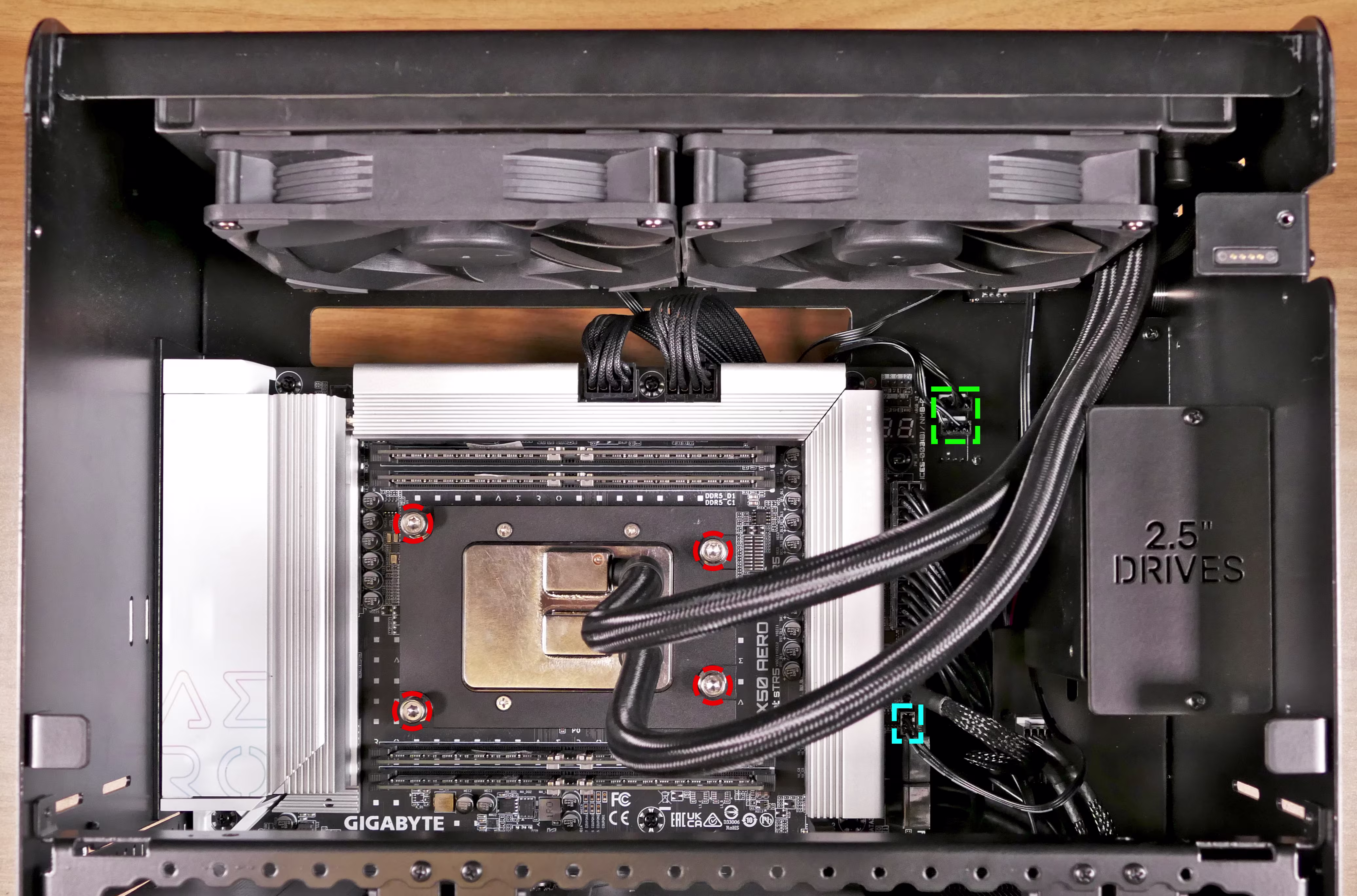
- Unplug the CPU cooler pump from the
SYS_FAN8_PUMPheader on the motherboard, highlighted cyan above. - Unplug the CPU cooler fans cable from the fan splitter board next to the motherboard, highlighted green above.
- While holding the radiator in place so it doesn’t fall, unscrew the eight silver screws holding the radiator on from the top of the chassis.
- If you aren’t replacing the CPU cooler or fans (but are replacing only the thermal paste and/or the CPU), you can skip this step and leave the radiator attached to the chassis.
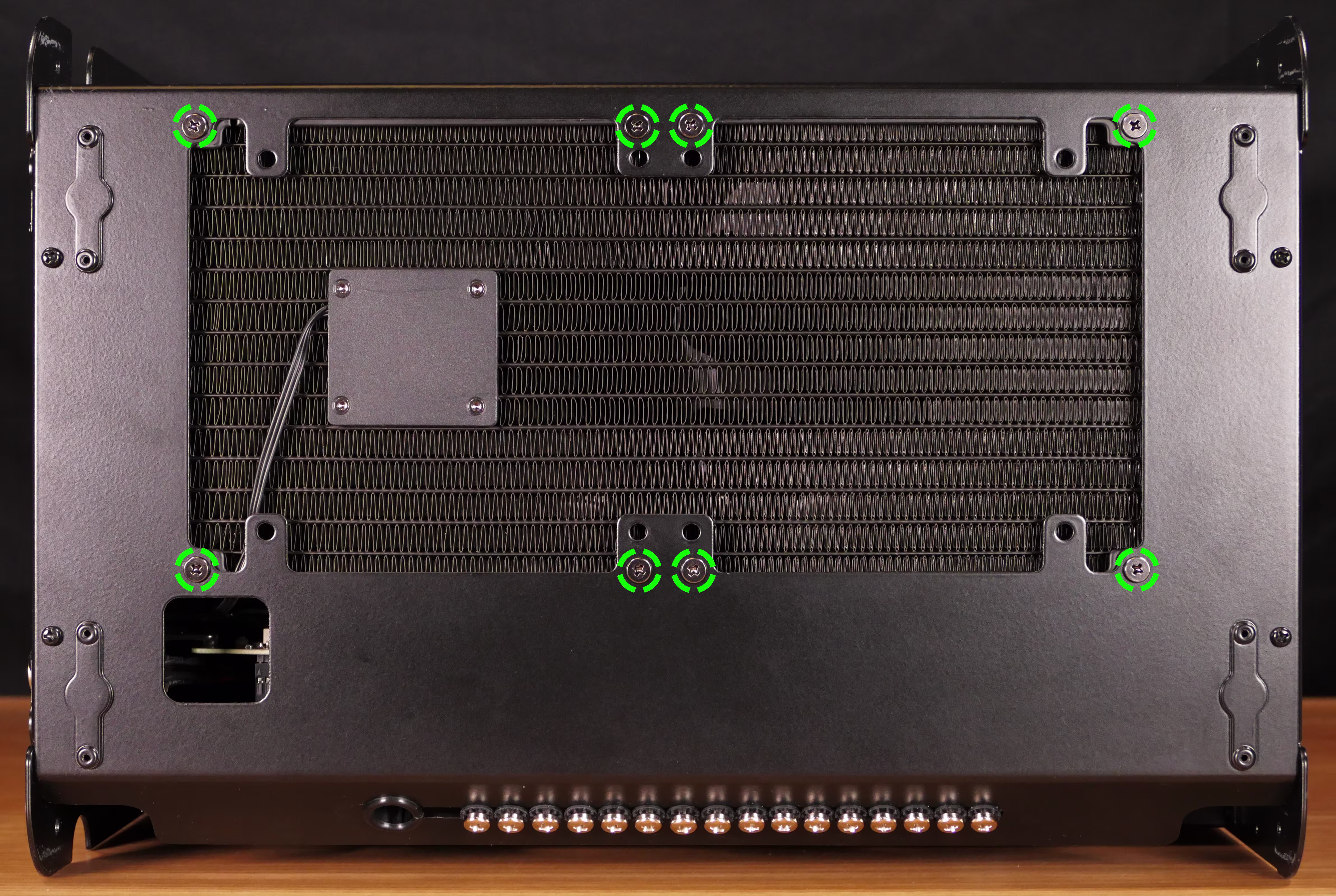
- Remove the CPU cooler pump and radiator (if applicable) from the chassis.
- Using a paper towel, clean the existing thermal paste off of the cooler and CPU. You may also use a small amount of rubbing alcohol if the old paste is dried or difficult to remove.
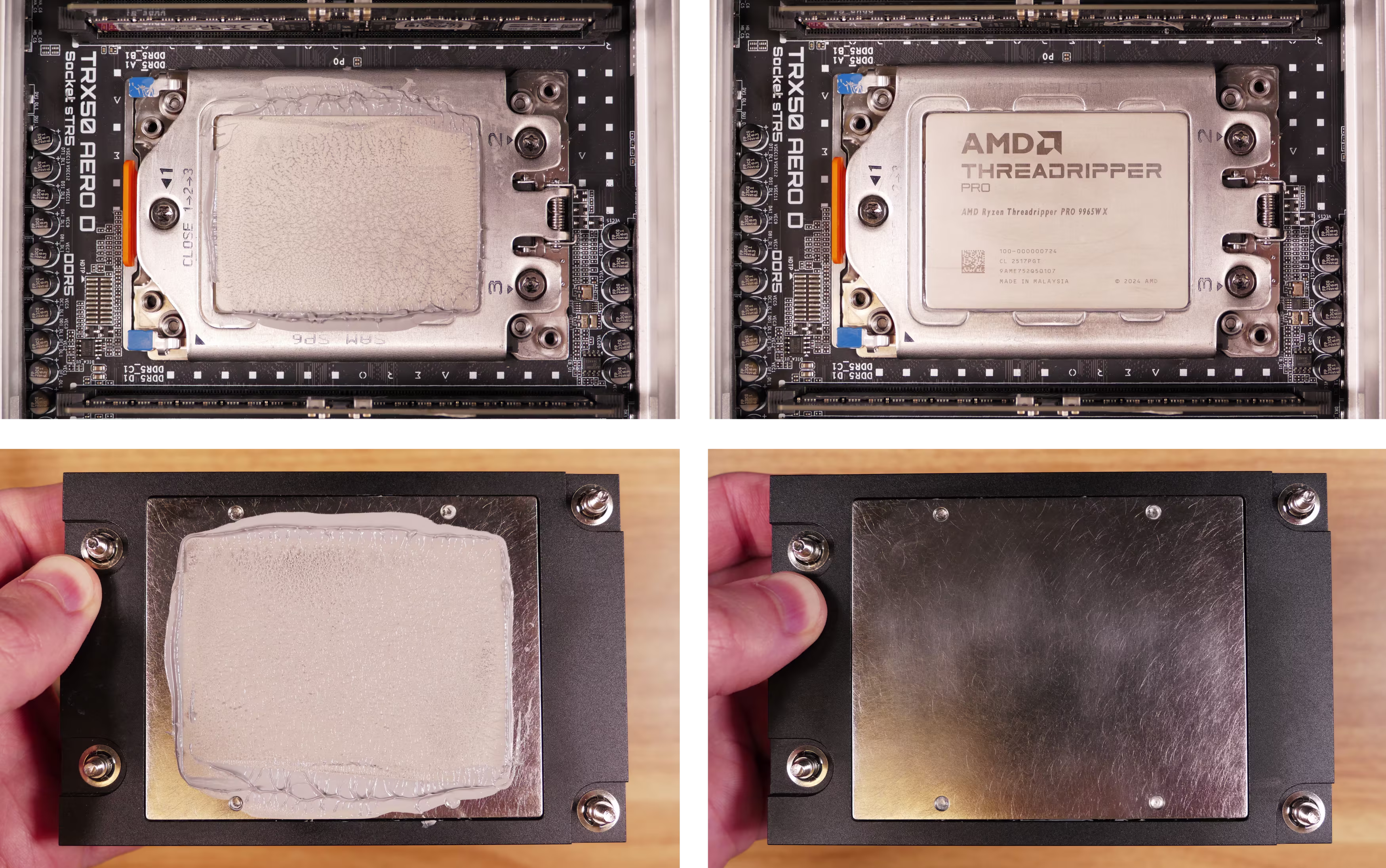
Steps to replace the CPU:
Section titled “Steps to replace the CPU:”- Using the AMD Threadripper torque screwdriver (or a compatible T20 screwdriver), loosen the three CPU bracket Torx screws in reverse order of the printed numbers (starting with #3).
- The screws are held captive and will not come out of the bracket.
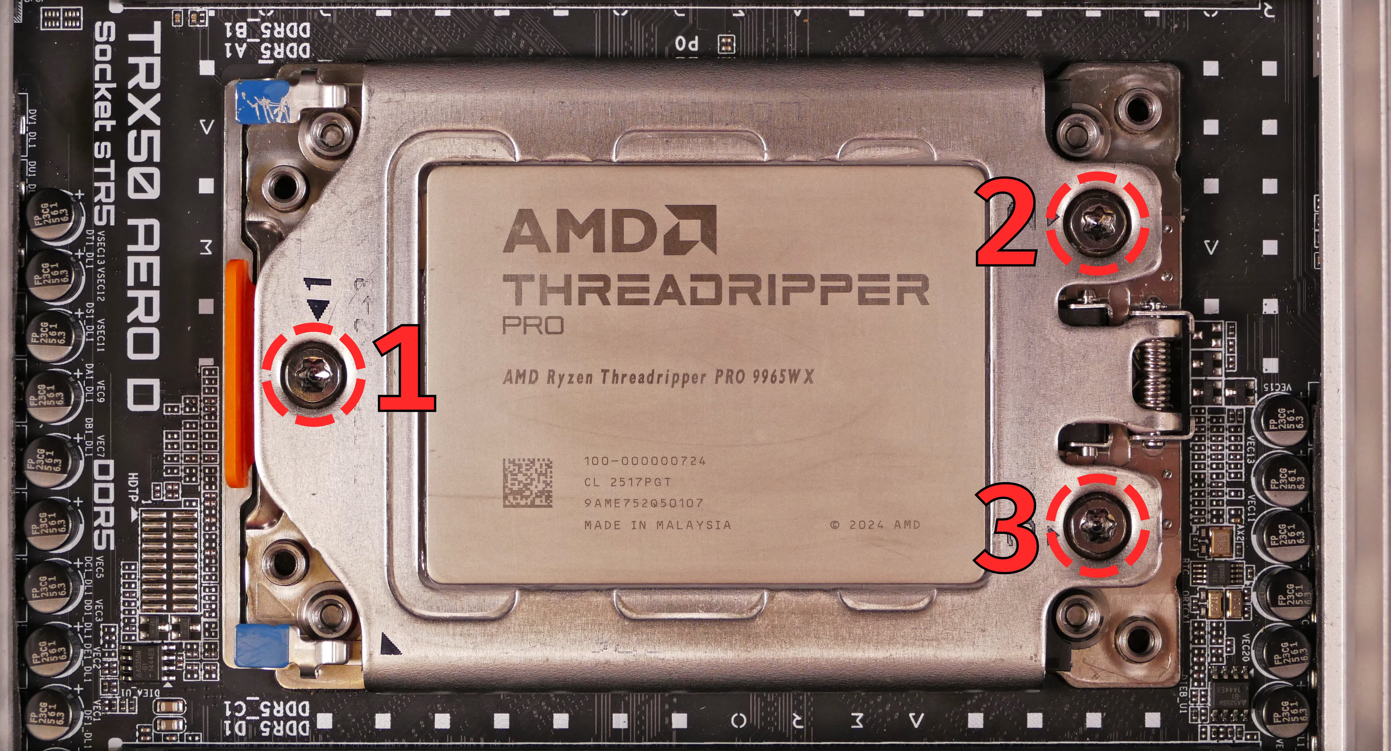
- The CPU bracket cover will spring up when all screws are fully loosened.
- If the bracket cover only partially opens, you may need to loosen screws #2 and/or #3 more.
- Additional thermal paste may be stuck underneath the bracket cover, and can be cleaned off after the bracket is opened.
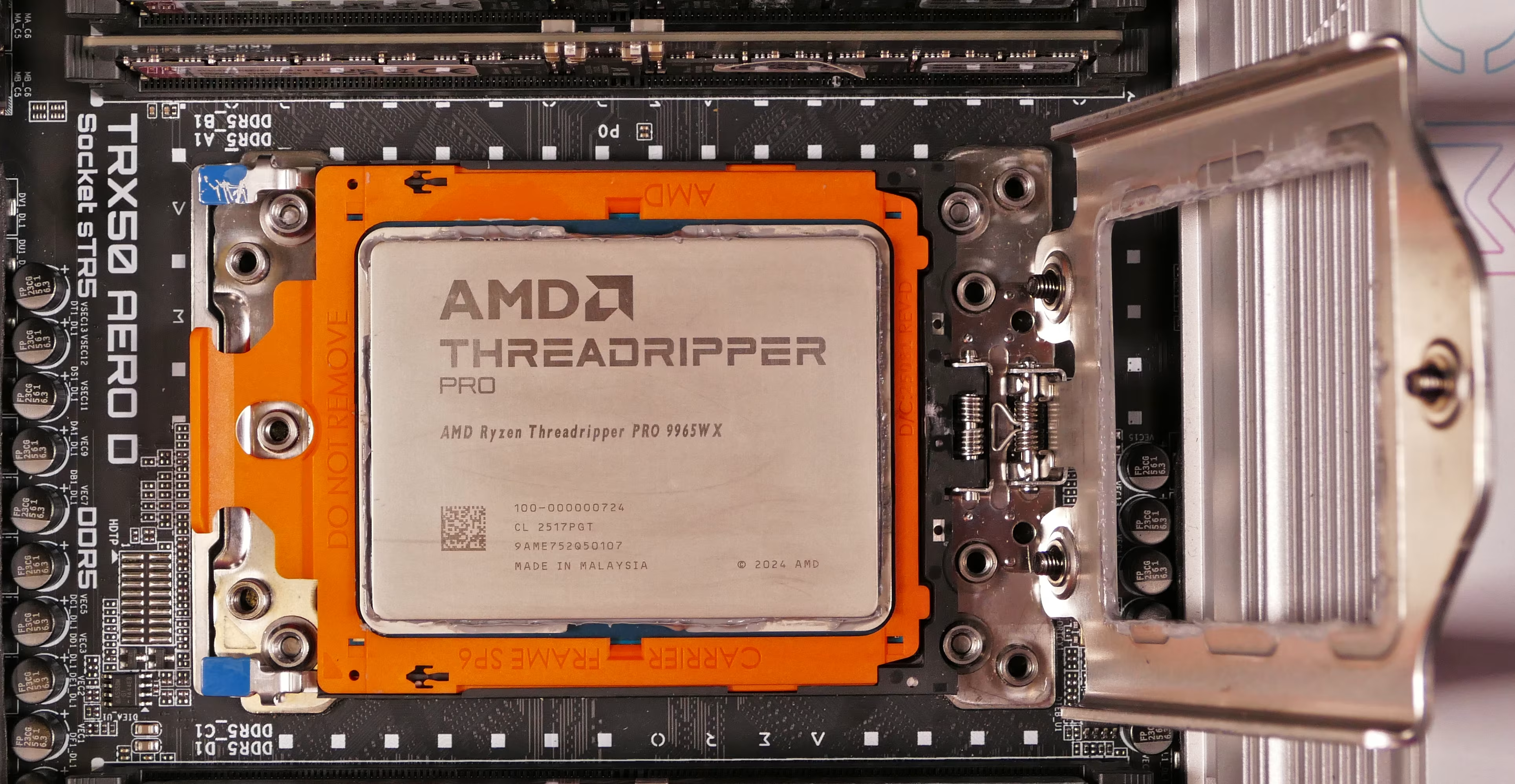
- Using the blue corner tabs (visible above), flip the orange CPU carrier frame up and away from the CPU socket.
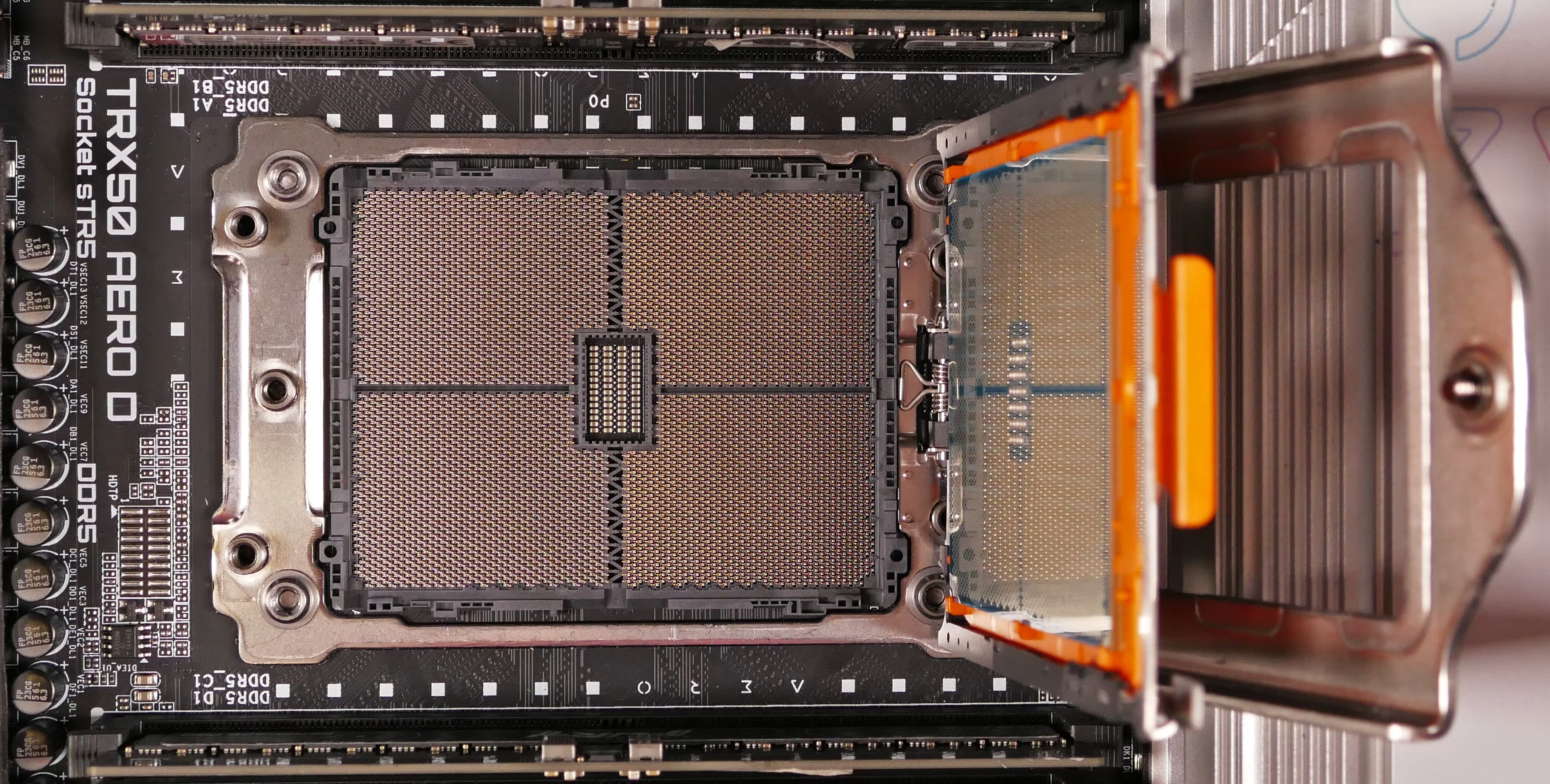
- Slide the CPU carrier tray out of the CPU bracket.
- Be careful not to bend any of the gold pins on the CPU socket, and do not touch the gold pads on the CPU.
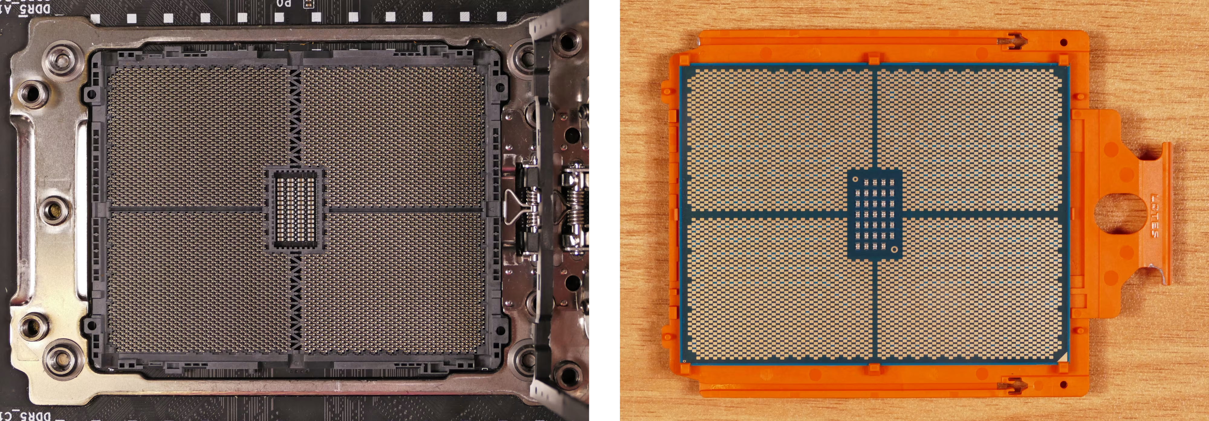
- Slide the new CPU’s carrier tray into the CPU bracket.
- AMD Threadripper CPUs come with carrier trays, so removing the CPU from the tray is generally not necessary.
- Flip the CPU bracket back down onto the socket, gently pressing the blue tabs to seat the CPU carrier tray onto the motherboard.
- Flip the CPU bracket cover back down.
- Screw the three Torx screws back into place in order of the printed numbers (starting with #1).
- The AMD Threadripper-branded tool applies 1.5 Nm of torque. When the screw is tight enough, it will give way.
- If you’re using a different screwdriver, use a torque tool to apply approximately the same amount of torque (1.5 Nm, or ~13.275 in-lb).
- If you’re using a screwdriver without a torque tool, try to tighten all three screws evenly. After re-assembling the computer, run a RAM test to ensure the CPU is secured with the correct amount of force.
Steps to replace the CPU cooler’s fans:
Section titled “Steps to replace the CPU cooler’s fans:”- Unscrew the four screws (per fan) holding the fan(s) onto the radiator.
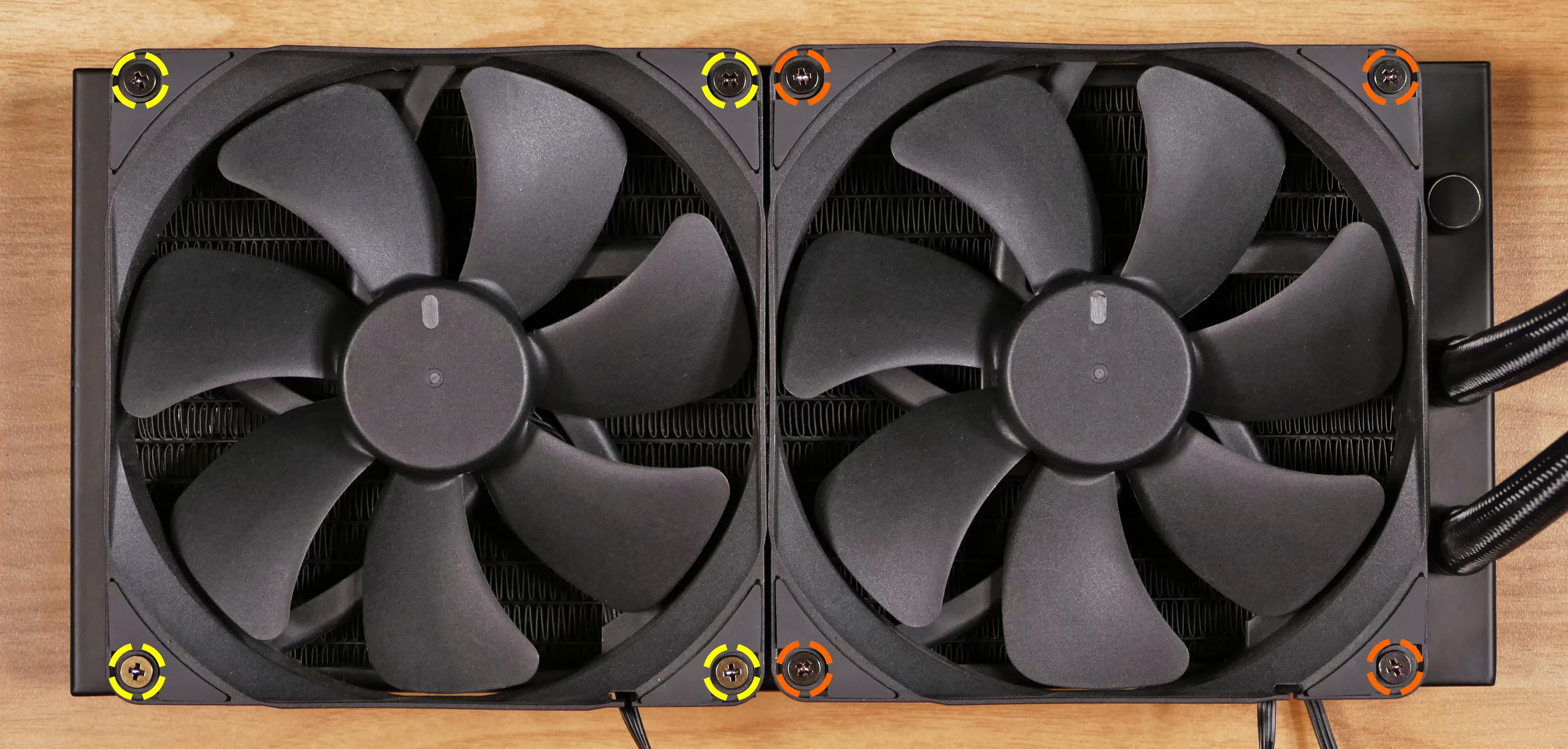
- Remove the old fan(s) from the radiator.
- Align the new fan(s) with the radiator.
- The spinning side of the fans should face away from the radiator.
- The cable from each fan should point towards the radiator’s cable.
- Screw in the new fan(s).
Steps to install the thermal paste/CPU cooler:
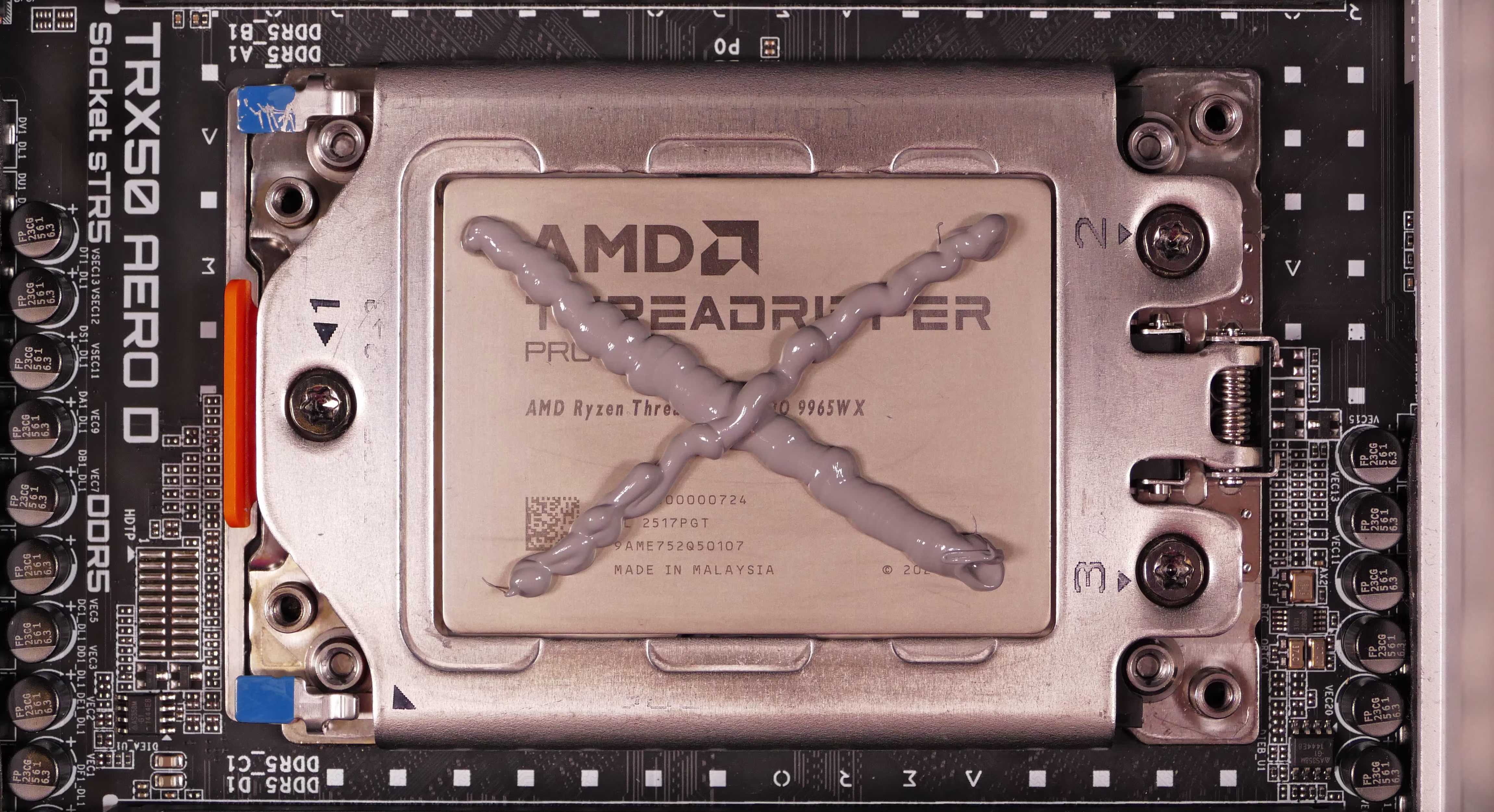
Section titled “Steps to install the thermal paste/CPU cooler:”- Draw an
Xshape of thermal paste onto the CPU.
- Place the all-in-one liquid cooler back into the chassis with the tubes running against the front of the chassis.
- Place the cooler plate back onto the four posts surrounding the CPU.
- The tubes running off of the cooler plate should be oriented towards the front of the chassis.
- Screw in the four Torx T20 screws to secure the cooler plate.
- Partially install each screw cap first, then fully tighten them in diagonal pairs.
- While holding the cooler’s radiator in place against the top of the chassis, screw it in from above using its eight screws.
- Again, partially install all eight screws first to ensure alignment, then go back and tighten them all.
- The radiator’s cable (which starts on the top) wraps around the side of the radiator through a channel in the radiator, and does not need to be run through any other part of the chassis.
- Set the computer upright.
- Plug the cooler pump into the
SYS_FAN8_PUMPheader at the top right corner of the motherboard. - Plug the fan cable into the fan splitter to the right of the motherboard.
- By default, the cable plugs into the bottom header; both headers provide the same signal.
- Pull the excess cooler pump cable through the cable management cutout above the motherboard, and secure it behind the motherboard along with the braided motherboard fan input cable using the velcro strap.
- Hold the liquid tubes against the back of the chassis and secure them in place using the velcro strap.
- Reinstall the top shell, front glass, and both side panels.
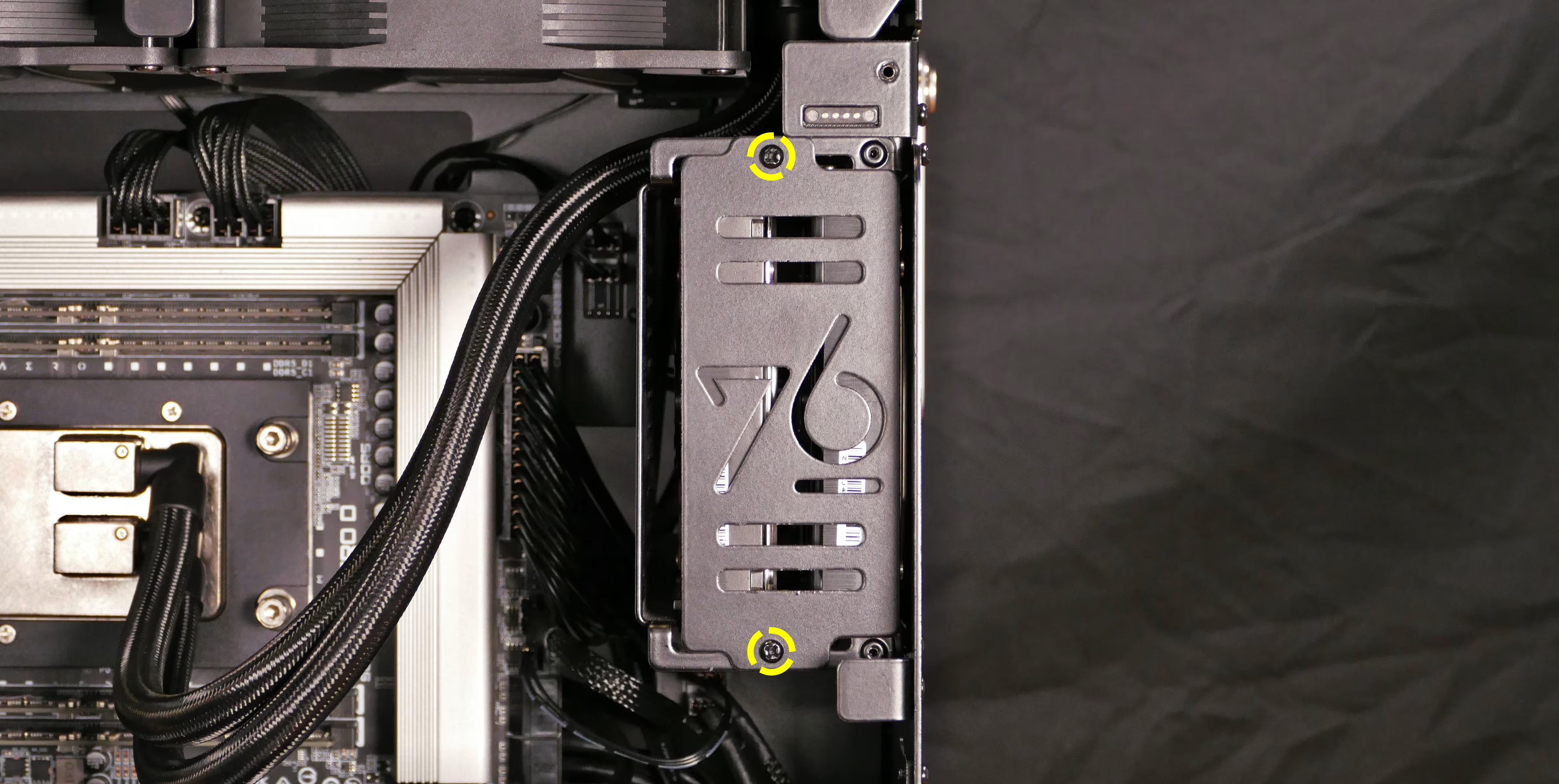
Replacing the Thelio Io board:
Section titled “Replacing the Thelio Io board:”Named after Jupiter’s moon Io, the Thelio Io daughterboard handles the front power button and fan control. If the Thelio Io board becomes defective, it can be replaced using the instructions below.
Part numbers:
- Thelio Major R5-N4 uses Thelio Io version 2 (PCB revision thelio_io_2.3).
Tools required: Cross-head (Phillips) screwdriver
Time estimate: 35 minutes
Difficulty: High ●
Steps to replace the Thelio Io board:
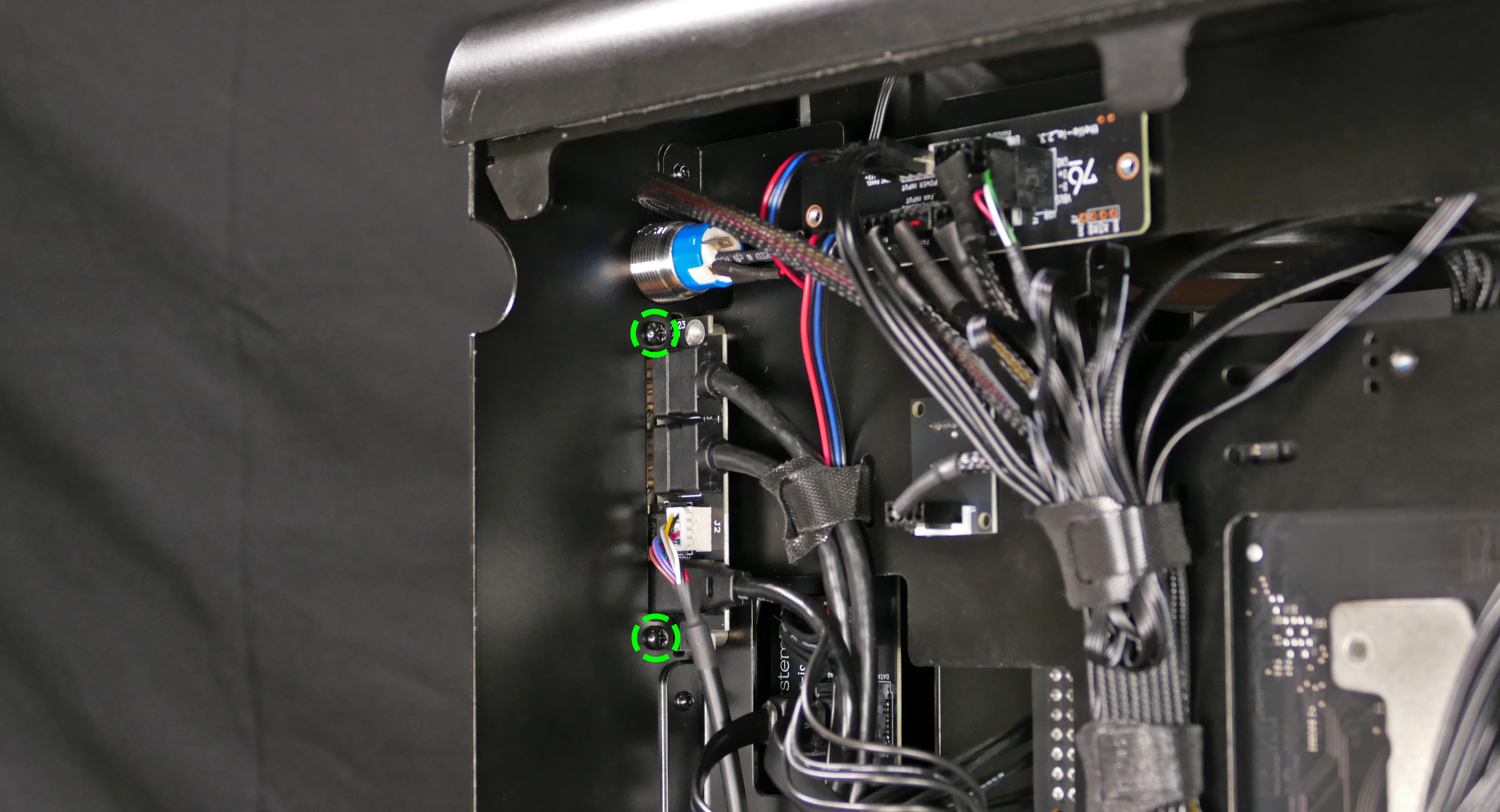
Section titled “Steps to replace the Thelio Io board:”- Follow the steps above to remove both side panels, remove the front glass, and remove the top shell.
- Unplug all wires from the Thelio IO board (behind the right side panel, near the power button).
- Lay the machine on its right side and follow the steps above to remove the CPU cooler radiator from the top of the chassis.
- It is not necessary to remove the CPU cooler pump from the CPU/motherboard, or to unplug the CPU cooler fans from the chassis.
- Stand the machine upright again.
- The CPU cooler radiator can rest on the GPU brace, but the weight of the radiator should not be placed directly onto the GPU. Alternatively, the GPU brace and GPU can be removed to provide more working room.
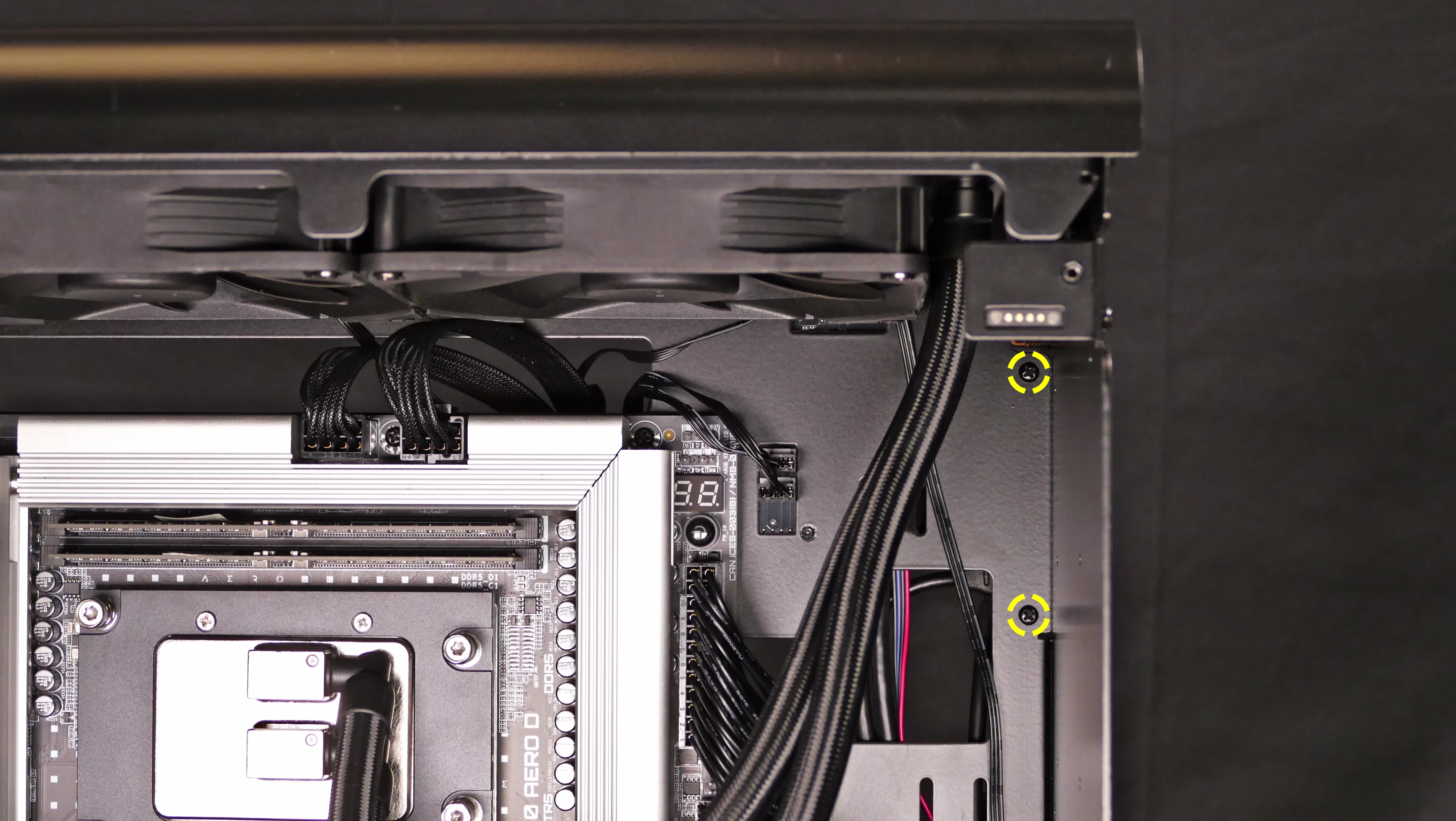
- Unscrew the two screws holding the Thelio Io board onto the chassis from the opposite side.
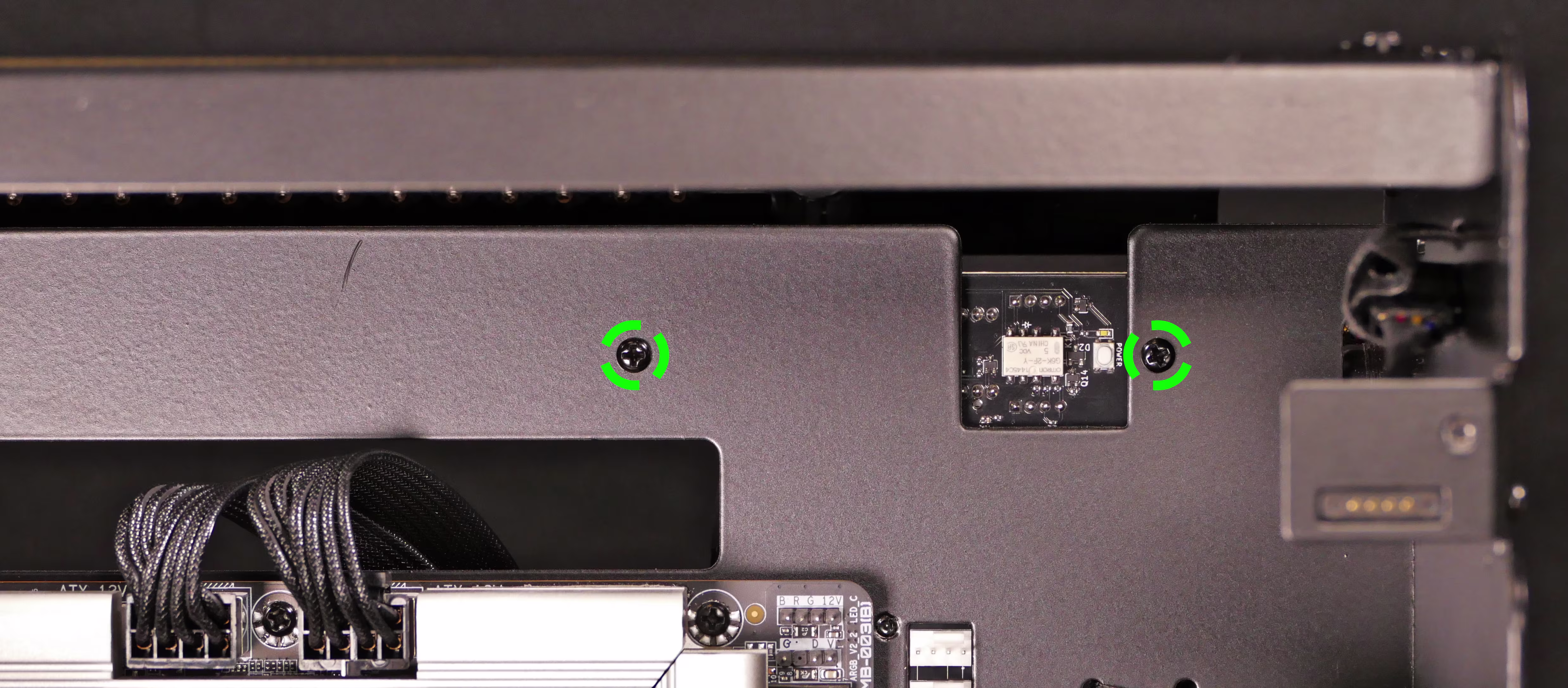
- Screw in the new Thelio Io board from behind.
- Orient the board so the System76 logo is upside-down (and so the
FRONT PANELheader is closest to the front panel).
- Orient the board so the System76 logo is upside-down (and so the
- Lay the machine on its right side, reinstall the CPU cooler radiator, and stand the machine upright again.
- Reconnect the wiring to the Thelio Io board.
- Reinstall the top shell, front glass, and side panels.
- If necessary, flash the appropriate Thelio Io firmware for your chassis revision.
- Boards provided by System76 for a specific system should already have the correct firmware, while boards repurposed from other systems may need flashing.
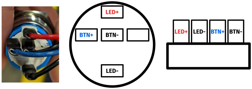
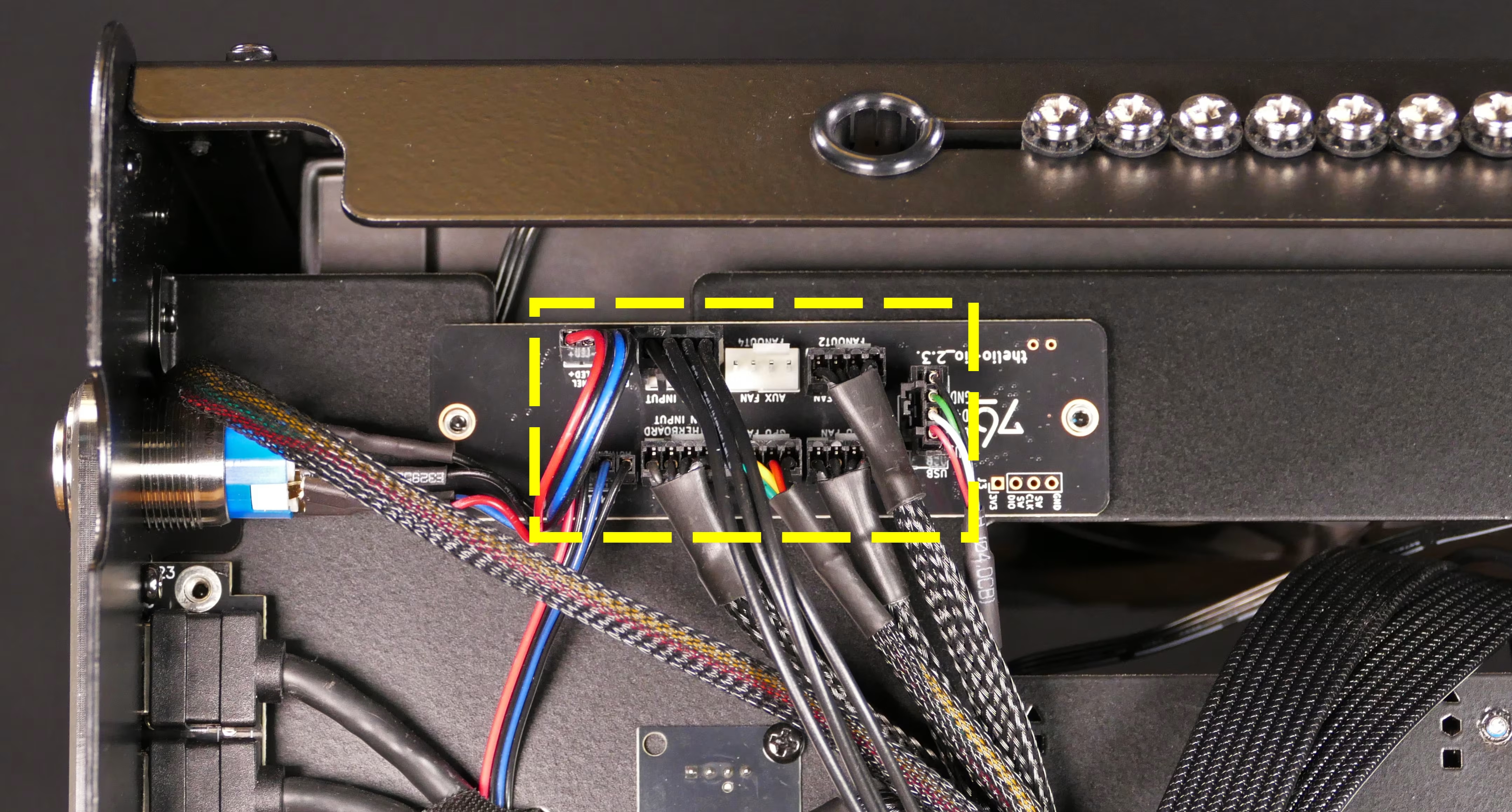
Thelio Io wiring guide:
Section titled “Thelio Io wiring guide:”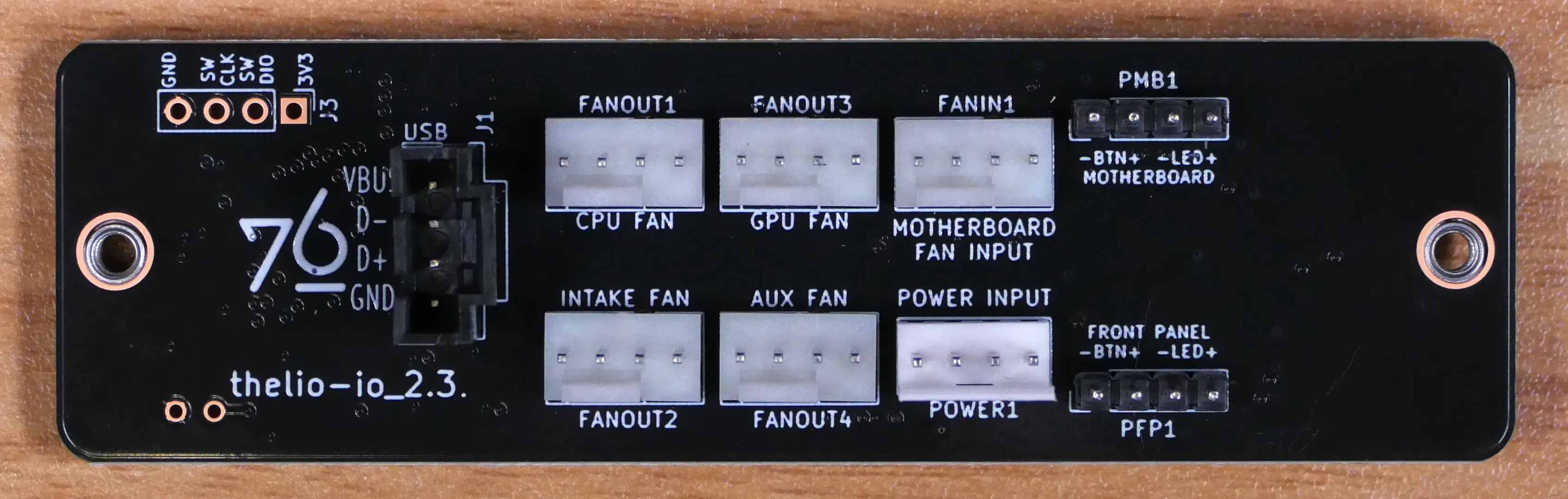
-
When wiring the Thelio Io board, refer to the port labels and the following guide.
PFP1/FRONT PANEL- to the power button on the front panel.- On the Thelio Io board, the wire color order (from left to right) is red, black, blue, black (the red wire connects to the
LED+pin).
- On the Thelio Io board, the wire color order (from left to right) is red, black, blue, black (the red wire connects to the
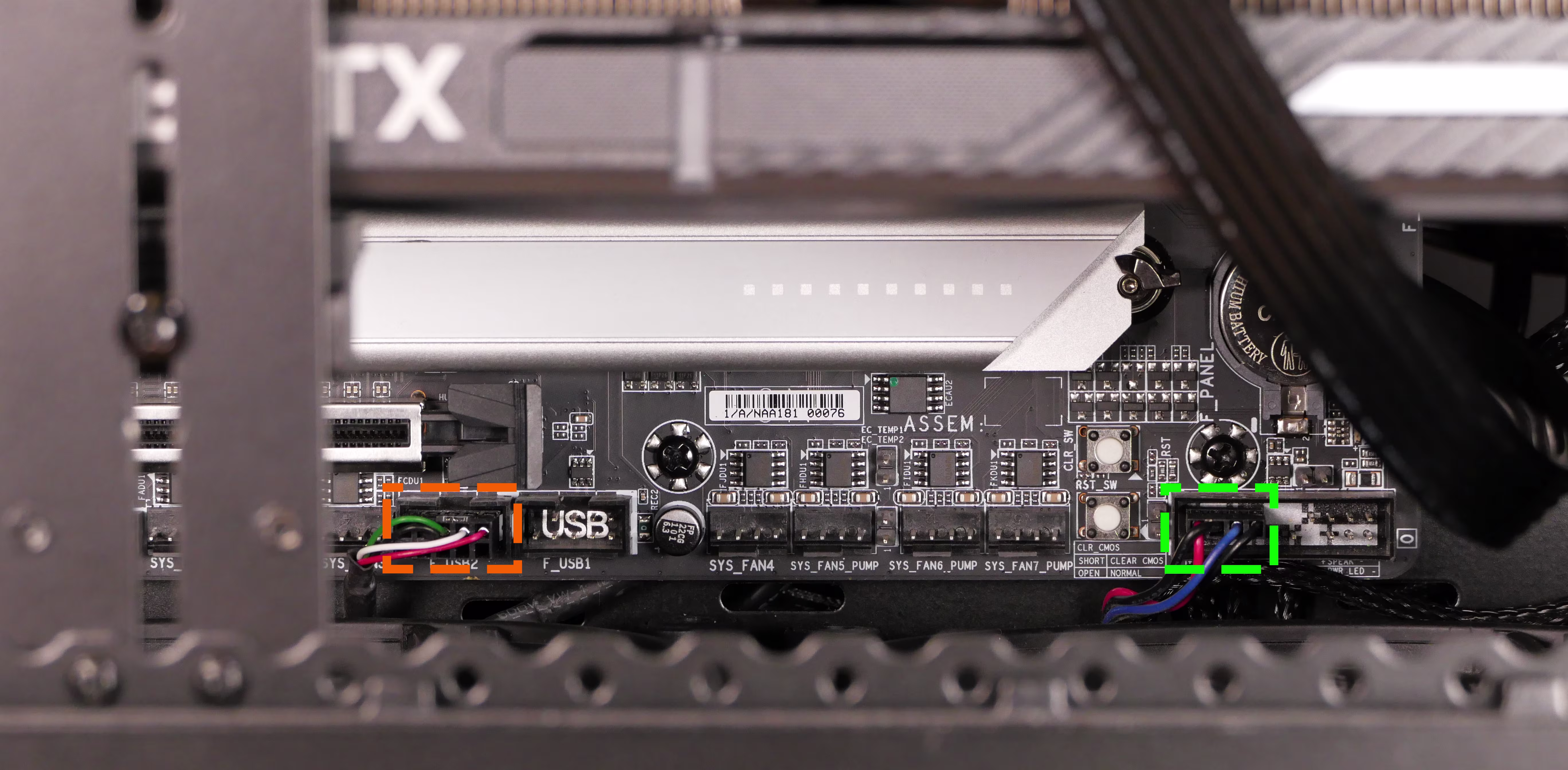
PMB1/MOTHERBOARD- to the first four pins of theF_PANELheader at the bottom right of the motherboard, highlighted green below.- On the Thelio Io board, the wire color order (from top to bottom) is red, black, blue, black.
- On the motherboard, the wire color order (from left to right) is red, black, blue, black.
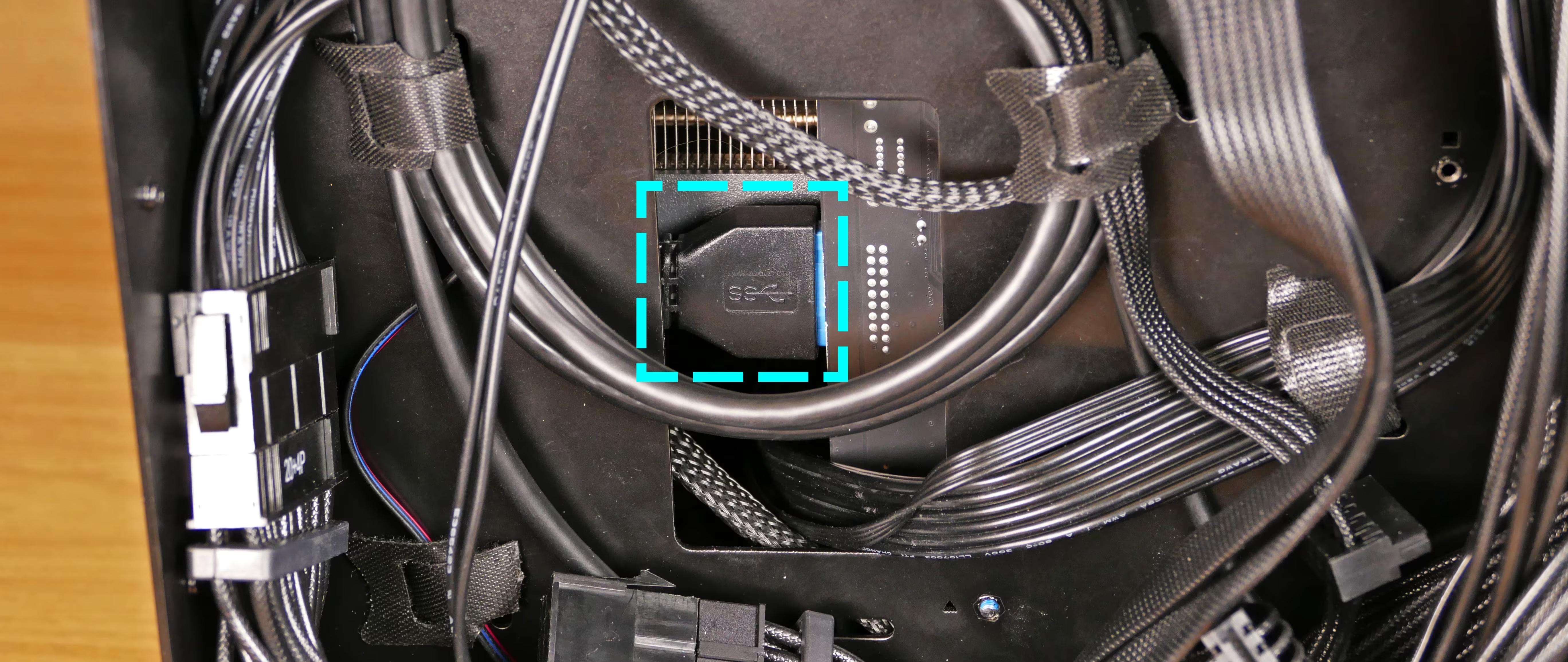
USB- to theF_USB2header at the bottom center of the motherboard, highlighted orange above.- A small clip needs to be held down to unplug this cable from the Thelio Io board.
POWER1/POWER INPUT- to the power supply via a 4-pin Molex adapter.- The white plastic clip needs to be held away from the connector to unplug this cable from the Thelio Io board.
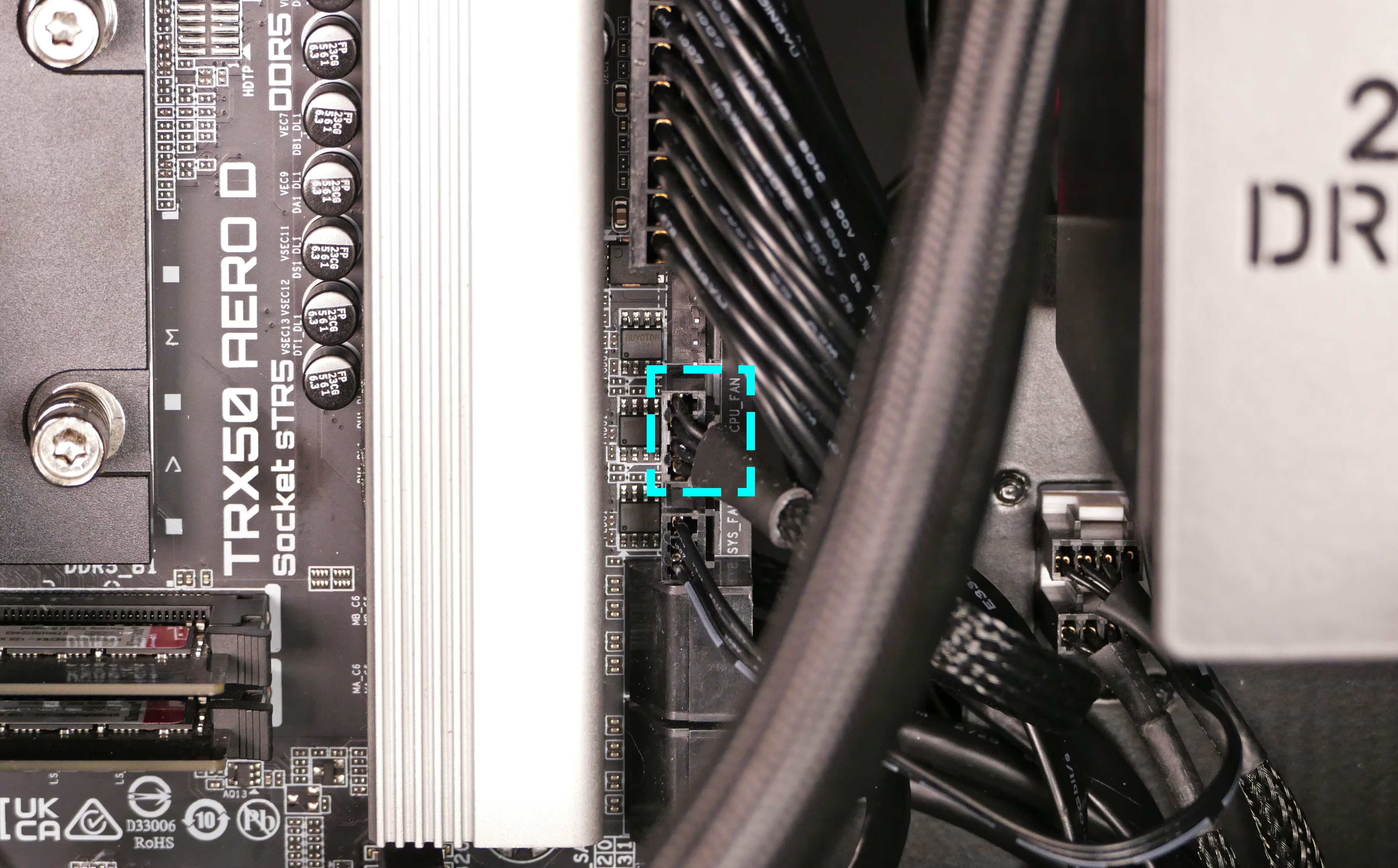
FANIN1/MOTHERBOARD FAN INPUT- to theCPU_FANheader on the right side of the motherboard, highlighted cyan below.
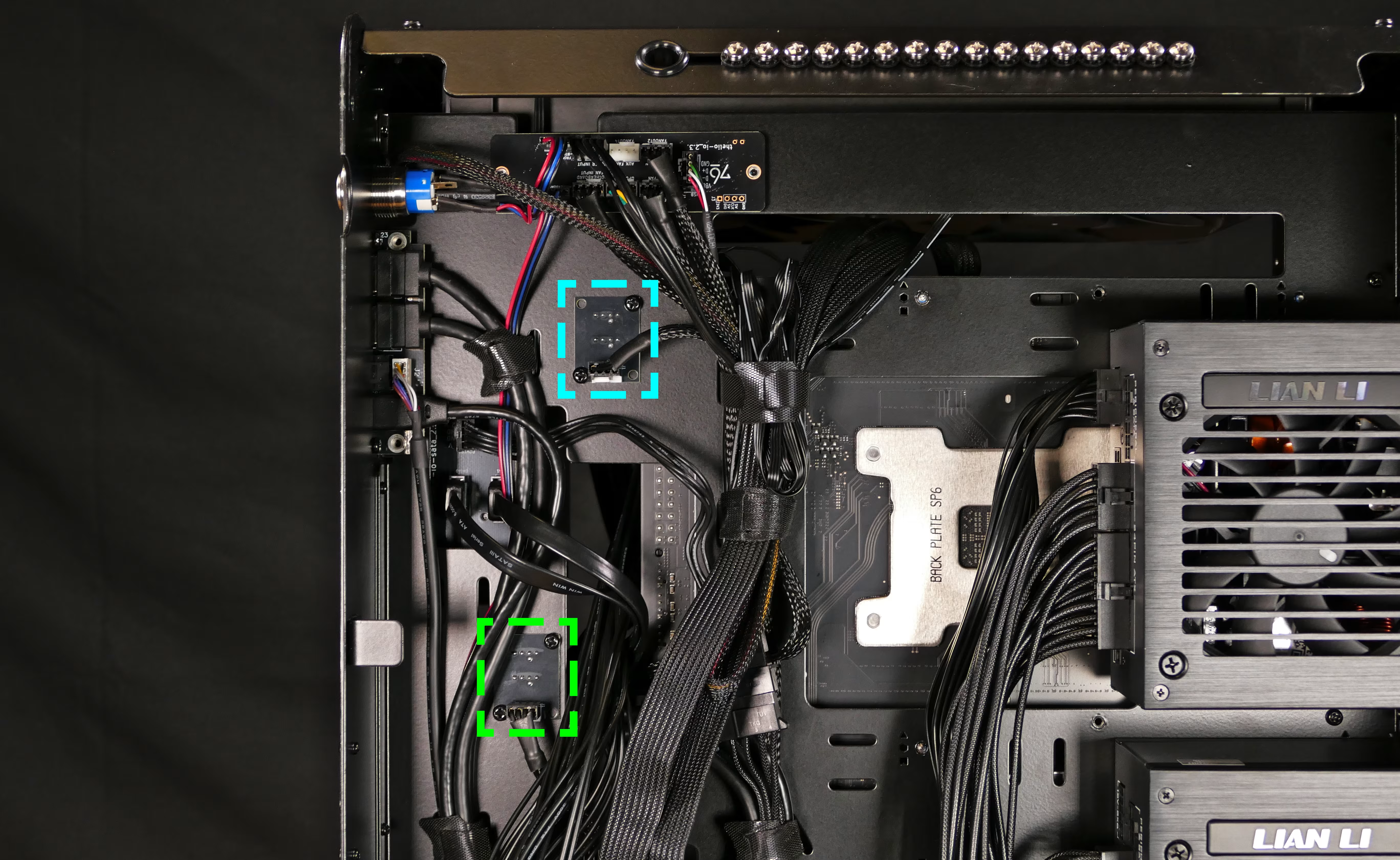
FANOUT4/AUX FAN- disconnected by default.FANOUT3/GPU FAN- to the bottom fan splitter (highlighted green below), which connects to both bottom case fans.
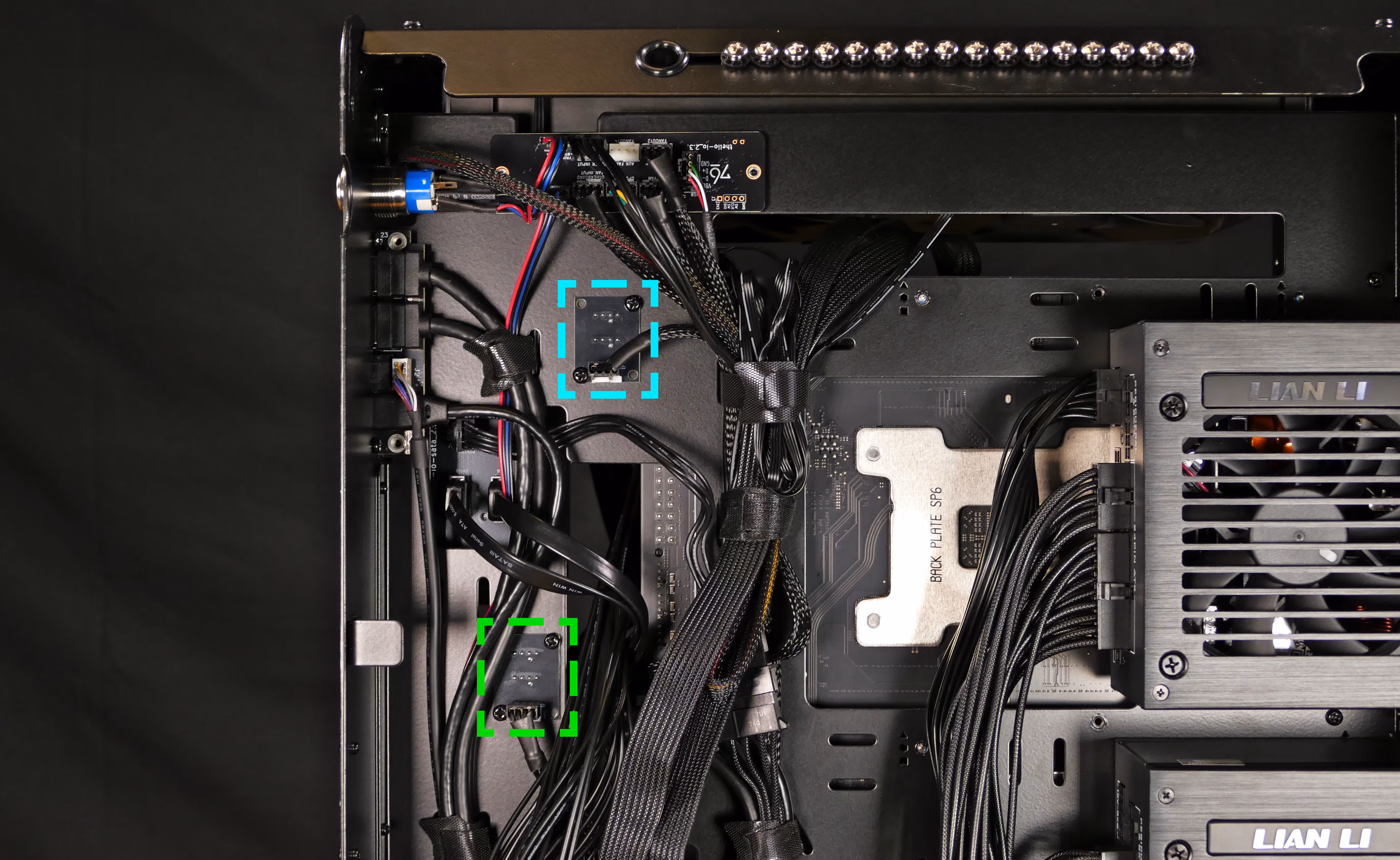
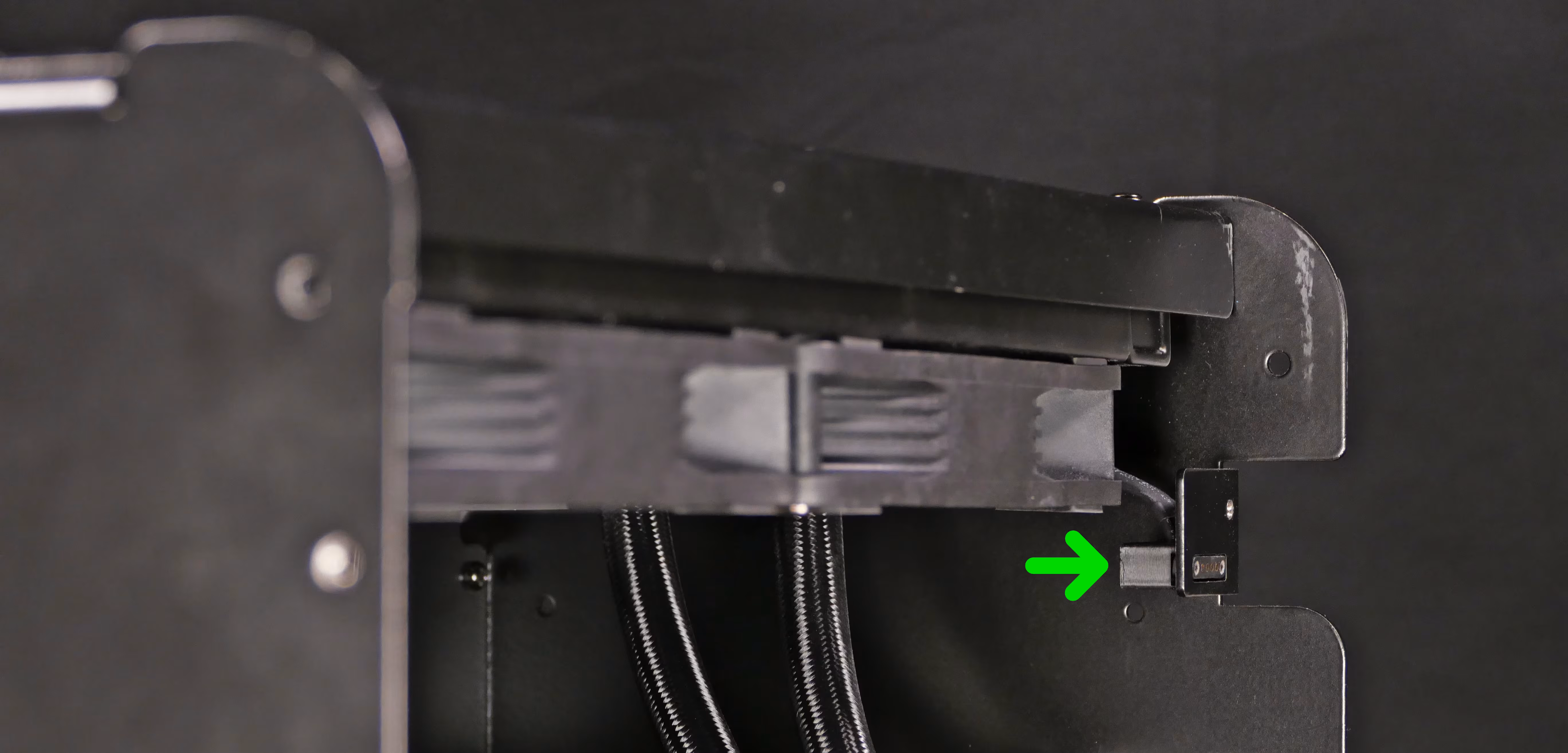
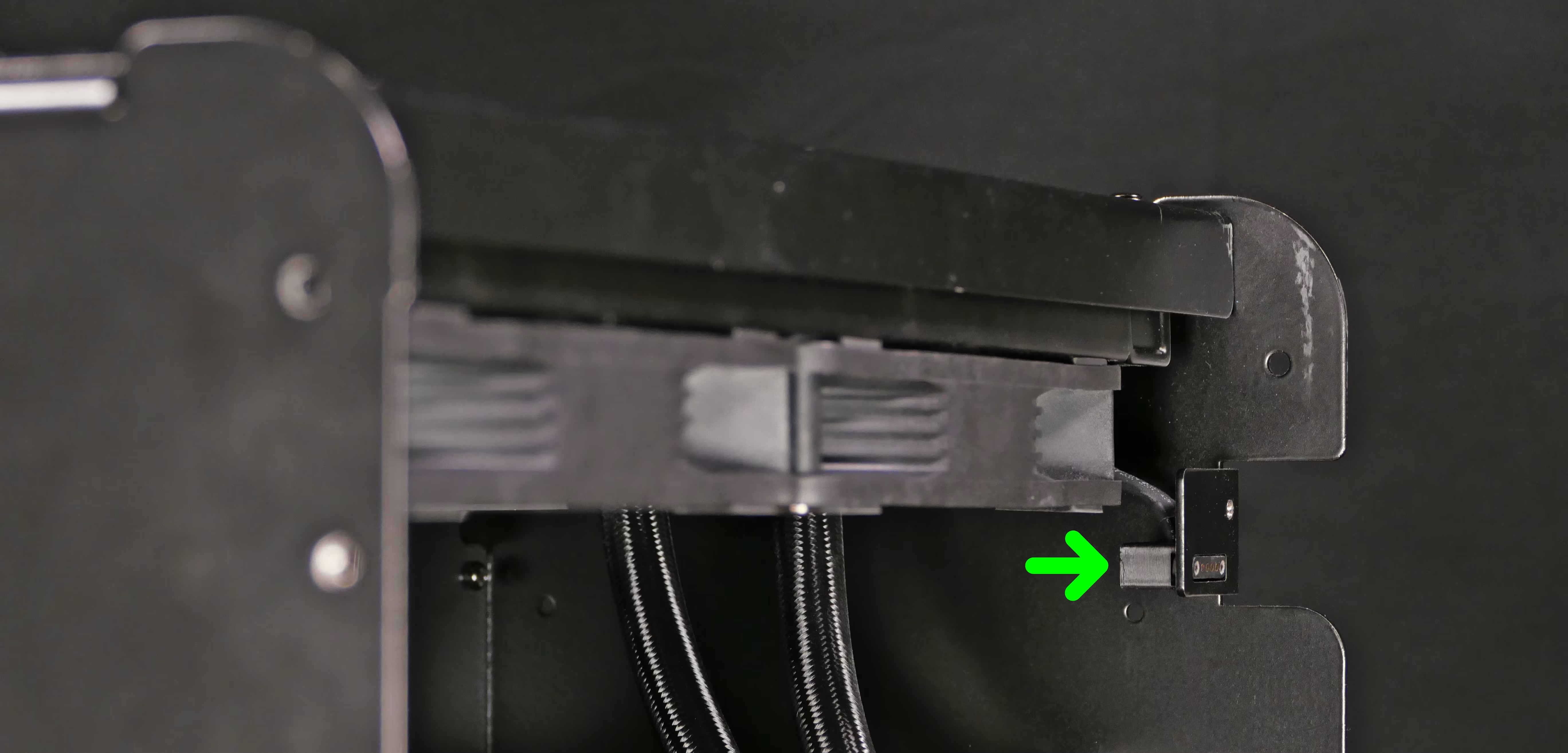
FANOUT1/CPU FAN- to the top fan splitter (connecting to the CPU radiator fans), highlighted cyan above.FANOUT2/INTAKE FAN- to the pogo pin connector for the left side panel fans.
Replacing the front I/O:
Section titled “Replacing the front I/O:”The front I/O board (containing the front USB and audio ports) can be replaced if necessary.
Part numbers:
- I/O board:
MYS7823(Rev.A01)
Tools required: Cross-head (Phillips) screwdriver
Time estimate: 35 minutes
Difficulty: High ●
Steps to replace the front I/O:
Section titled “Steps to replace the front I/O:”- Follow the steps above to remove both side panels.
- If a front 2.5“ or 3.5“ drive cage is installed, remove the front glass and remove the front 2.5“ or 3.5“ drive cage.
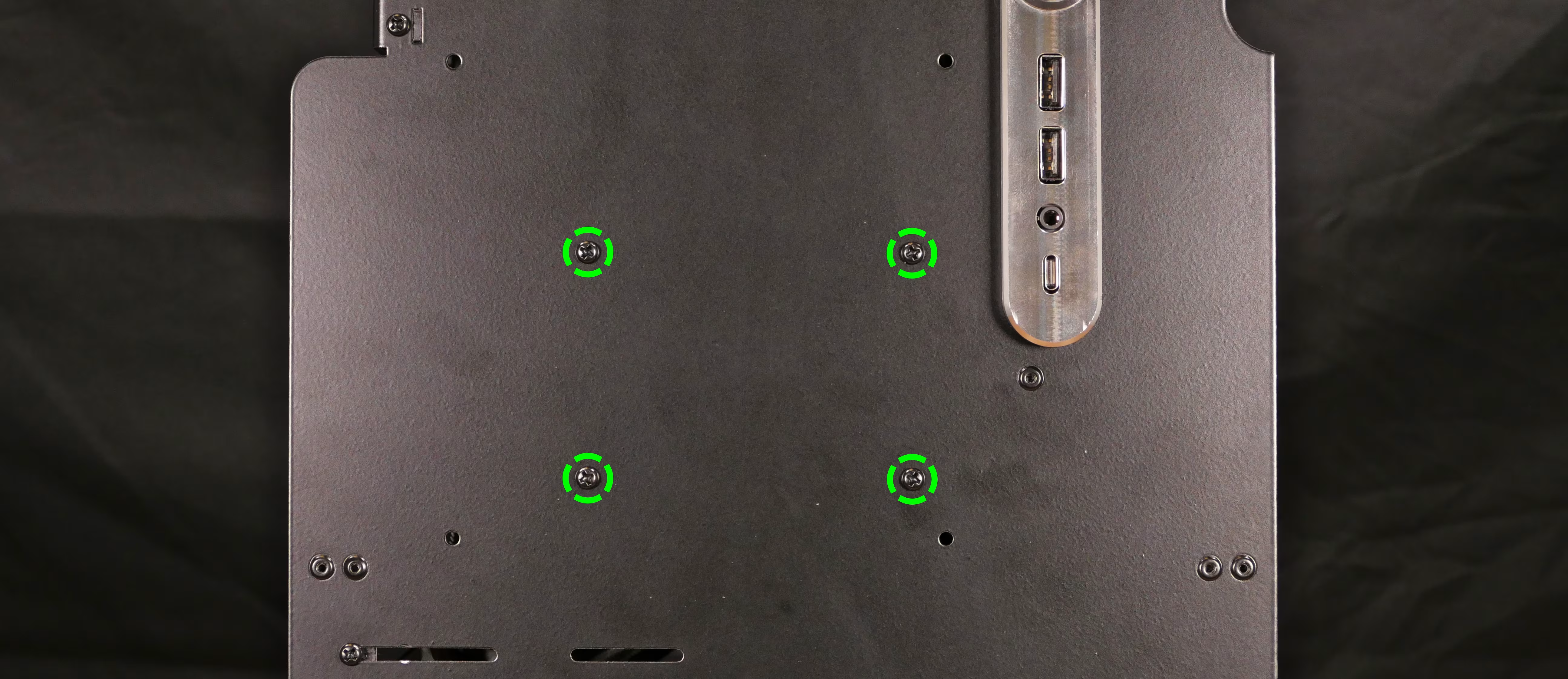
- From the left side of the case, unscrew the two screws holding the I/O board in place.
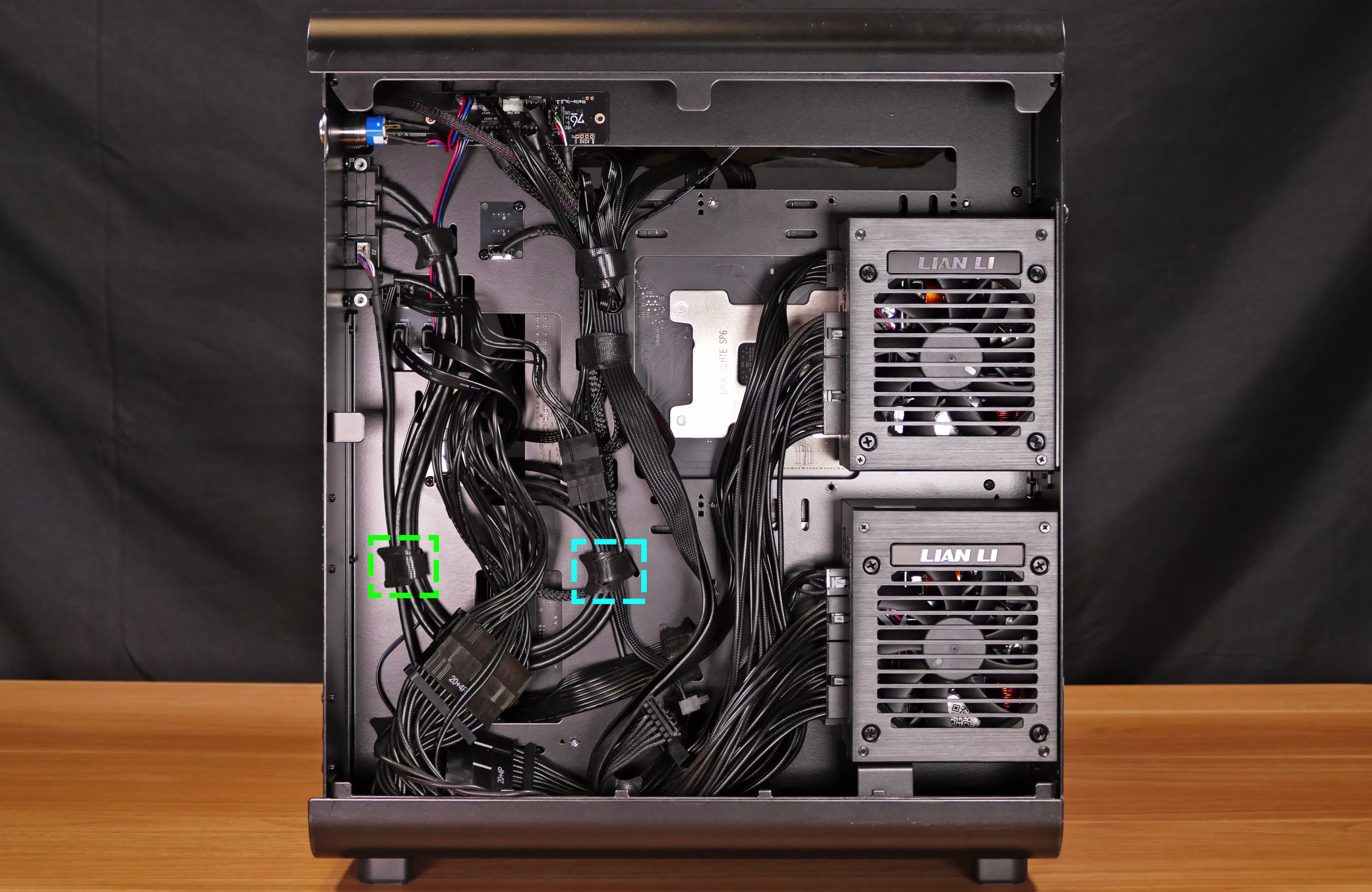
- From the right side of the case, unfasten the velcro straps holding the I/O board’s cabling in place.
- All four cables pass through the first velcro strap (highlighted green below).
- The three USB cables pass through the last velcro strap (highlighted cyan).
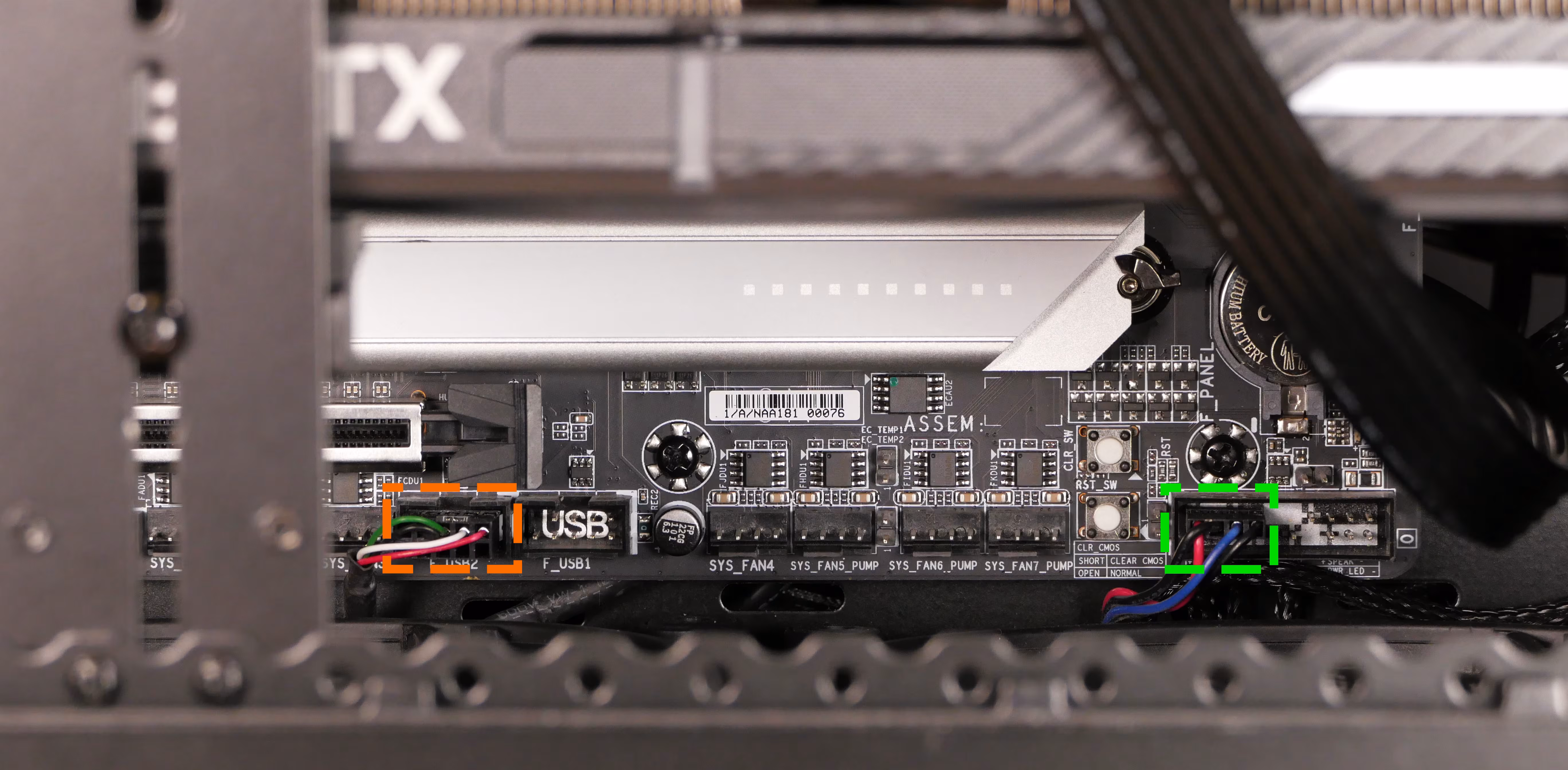
- Unplug the I/O board’s cables from the motherboard.
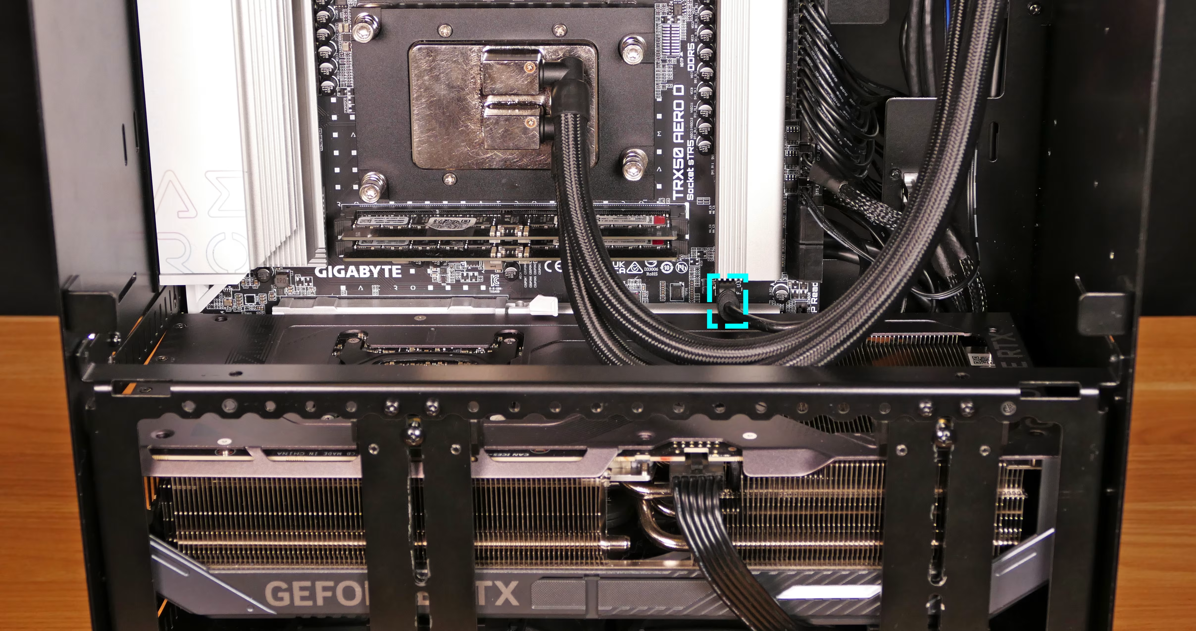
- The USB Type-C port’s cable plugs into the
F_U320Gheader on the motherboard, above the GPU.
- The USB Type-A ports’ cables plug into the
F_U32header on the right side of the motherboard, which can be accessed via the chassis cutout between the two velcro straps.- Alternatively, you can remove the GPU to access this port from the opposite side.

- Alternatively, you can remove the GPU to access this port from the opposite side.
- The 3.5mm jack’s cable plugs into the
F_AUDIOheader at the bottom left of the motherboard.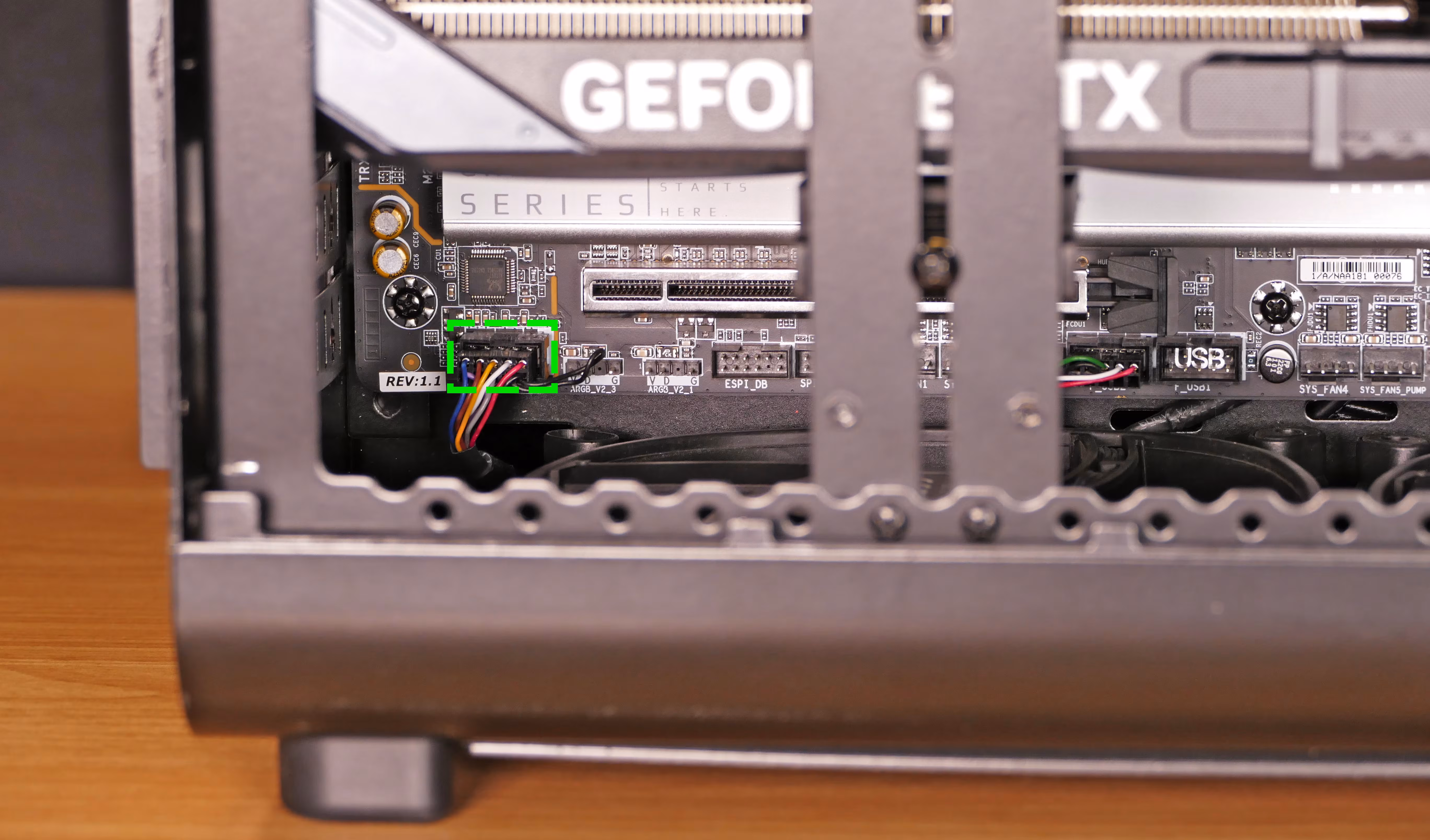
- The USB Type-C port’s cable plugs into the
- Plug the new I/O board’s cables into the same headers.
- Fasten the new I/O board’s cables into the velcro straps.
- Slide the new I/O board into its cutout on the front of the chassis, then screw it into place.
- Ensure the ports extend all the way through the front accent’s cutouts before inserting the screws.
- Reinstall the front drive cage, front glass, and side panels as applicable.

Replacing the power button:
Section titled “Replacing the power button:”The power button can be replaced independently of the surrounding front panel.
Part numbers:
- Power button:
PB-02A-19-RF-BOW(stainless steel, white LED)
Tools required: Cross-head (Phillips) screwdriver
Time estimate: 35 minutes
Difficulty: High ●
Steps to troubleshoot the power button:
Section titled “Steps to troubleshoot the power button:”- Ensure the power supply switch on the back of the computer is set to the
1position.- If it was set to
0, change it to1and try powering on the computer again. - If your system has two power supplies, make sure both are set to
1.
- If it was set to
- Follow the steps above to remove the left side panel.
- Press the white
POWERbutton on the right side of the Thelio Io’s chassis cutout, located behind the radiator fans at the top of the chassis (and behind any installed 2.5“ or 3.5“ drive cages in the front of the chassis).
- If the system powers on with the internal
POWERbutton, then the front power button or its connection to the Thelio Io board may be faulty. Proceed to the next section to try re-plugging or replacing the power button.- If the system doesn’t power on with the internal
POWERbutton, the Thelio Io board or another component (such as the motherboard or power supply) may be faulty, or a connection between those components may be missing. Check the Thelio Io wiring and the power supply cabling.
- If the system doesn’t power on with the internal
Steps to replace the power button:
Section titled “Steps to replace the power button:”- Follow the steps above to remove both side panels and remove the front glass.
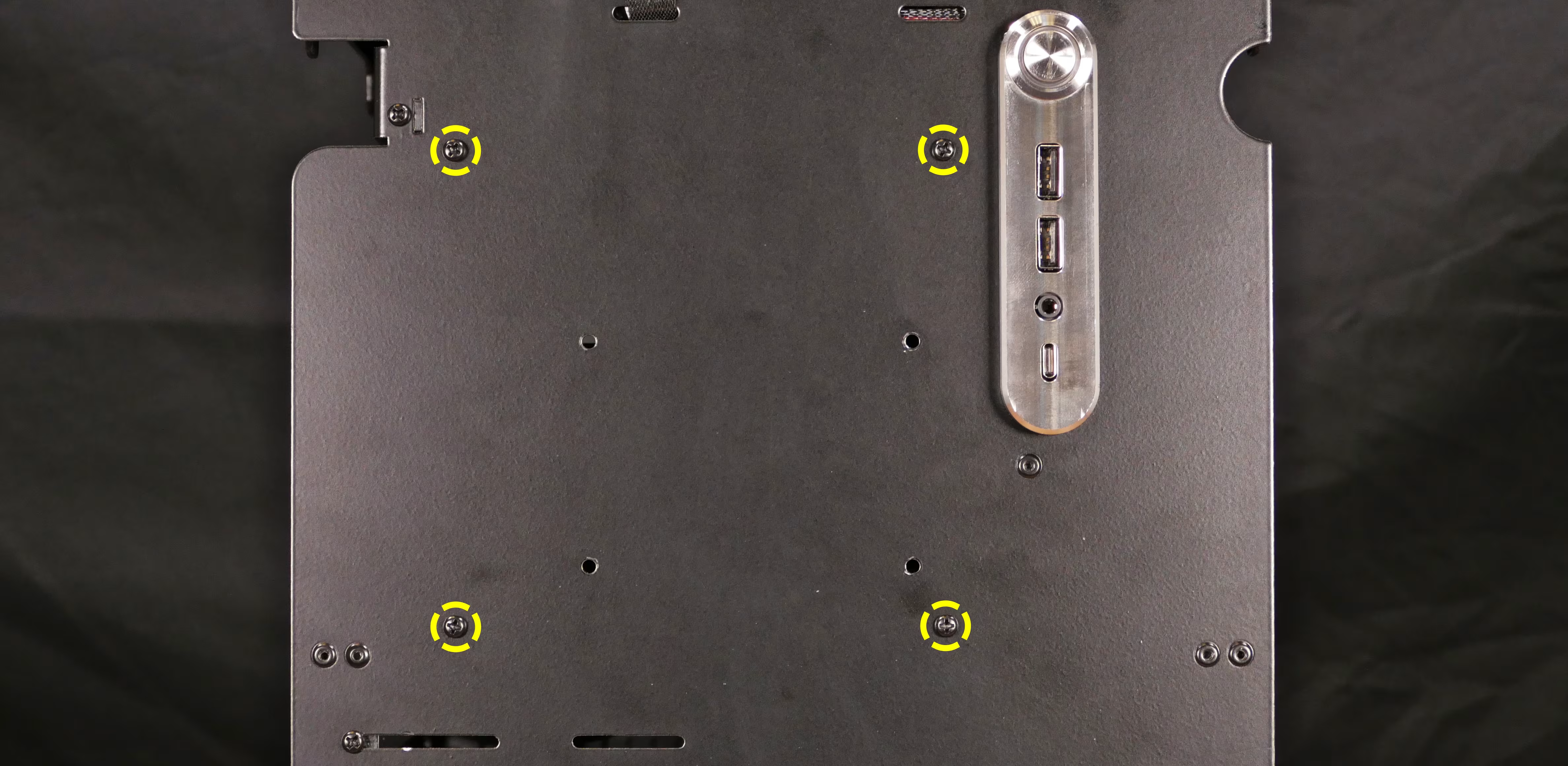
- Unscrew the two screws holding the front accent onto the chassis.
- Unplug the power button from the
FRONT PANEL/PFP1port at the top left of the Thelio Io board. - Unscrew the power button through the front of the accent.
- A gripping pad or tool may be required to loosen the button.
- Screw the new power button into the accent.
- Plug the new power button into the
FRONT PANEL/PFP1port on the Thelio Io board with the red wire on the left (facing the power button).- The wires connected to the power button should be laid out as shown below:
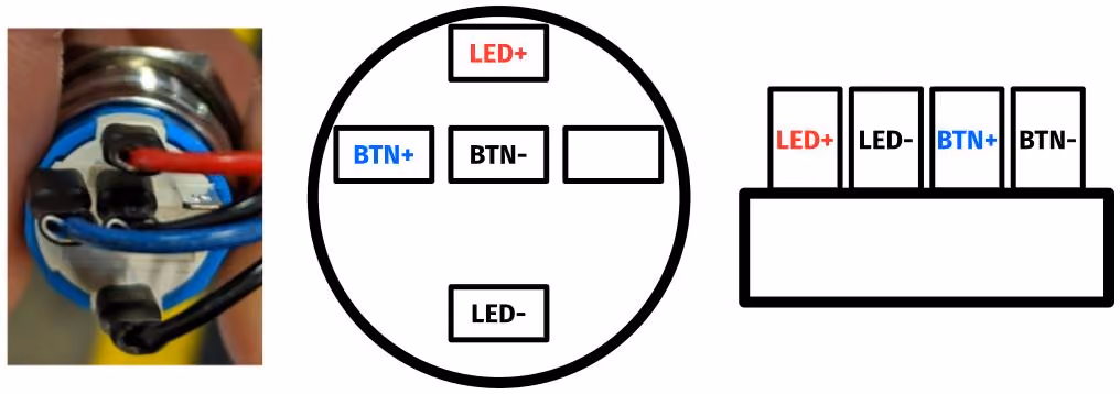
- The wires connected to the power button should be laid out as shown below:
- Place the front accent against the front panel and screw it into place from behind.
- Ensure the front I/O ports are properly aligned within the accent while screwing in the accent. If necessary, unscrew the front I/O ports to adjust them.
- Reinstall the front glass and side panels.