Pangolin Pro (Parts & Repairs)
Many components in your Pangolin Pro can be upgraded or replaced as necessary. Follow these step-by-step guides for instructions:
- Removing the bottom cover
- Replacing the RAM
- Replacing an M.2/NVMe SSD
- Removing the battery
- Reseating the WiFi/Bluetooth antennas
- Replacing the fans/heatsink/thermal paste
- Replacing the speakers
Removing the bottom cover:
Removing the cover is required to access the internal components. Prior to removing the cover, ensure the AC power is unplugged and all peripherals (including SD cards and USB drives) are unplugged or removed from the system.
Part numbers:
- The bottom panel’s part number is
839-ND16ARL.
Tools required: Cross-head (Phillips) screwdriver, plastic spudger
Time estimate: 5 minutes
Difficulty: Easy ●
Steps to remove the bottom cover:
- Place the machine lid-side down.
- Use a soft surface (such as a towel) to avoid scratches.
- Remove the 9 bottom panel screws.
- The front four screws are mounted at an angle into the machine; hold the screwdriver at an angle for the easiest removal/installation.
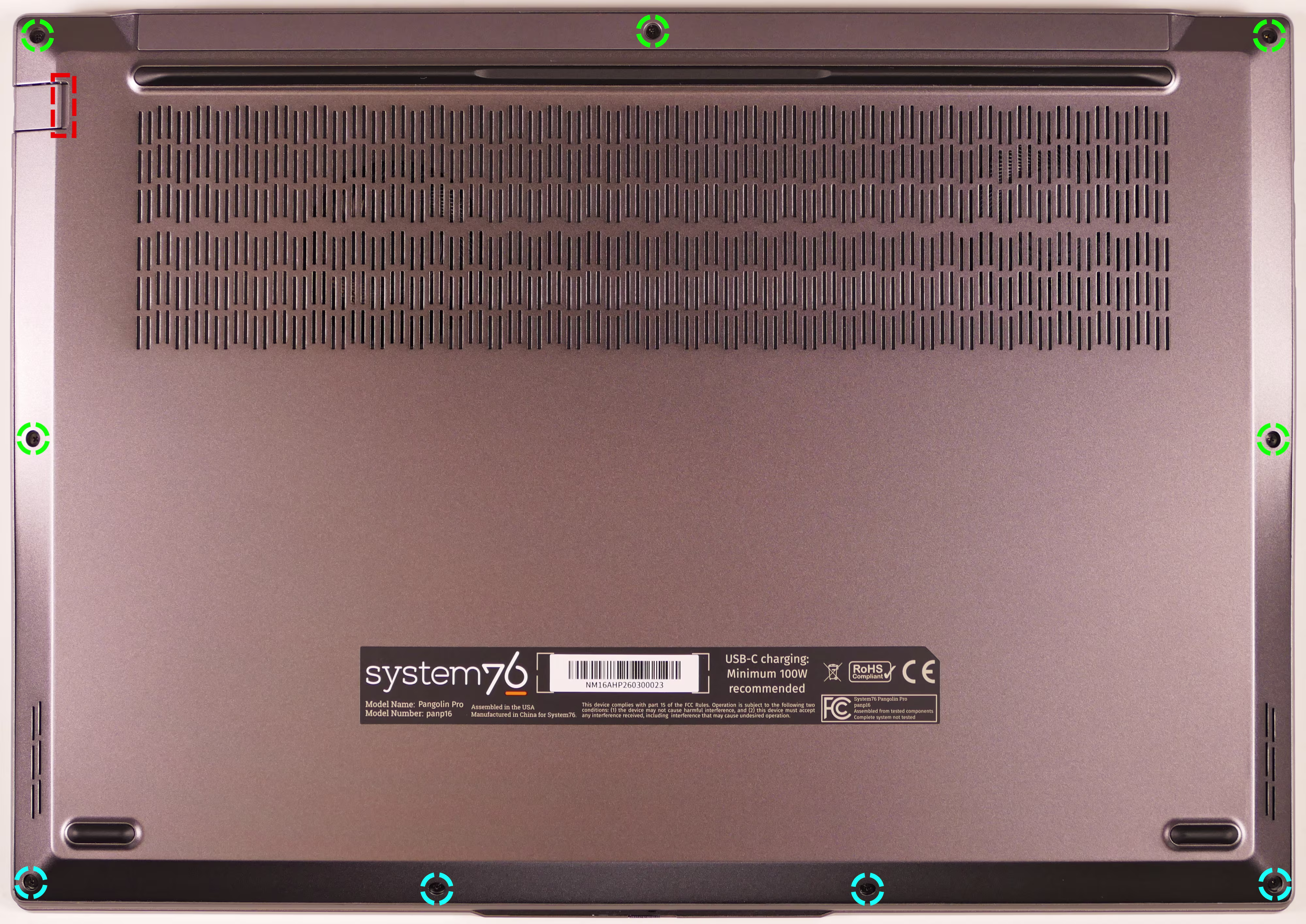
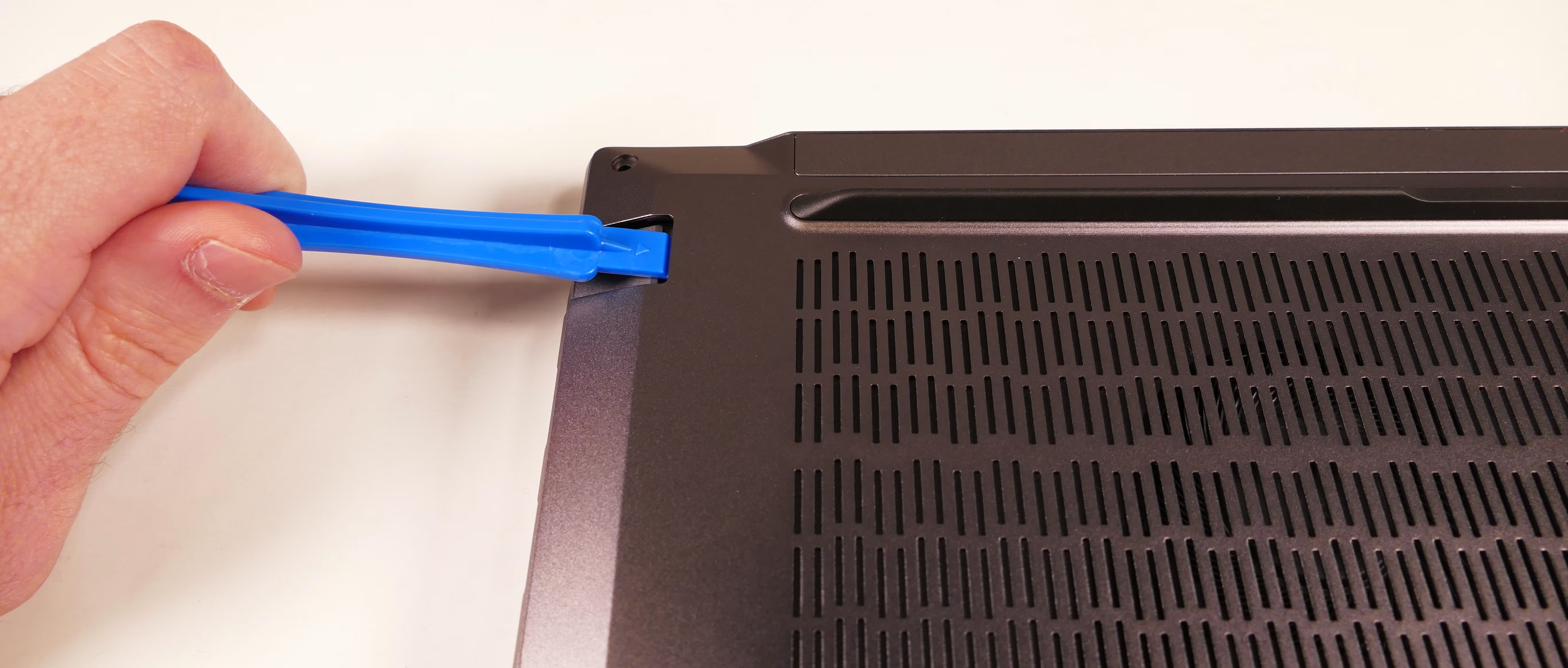
- Use a plastic spudger tool to pry the panel away from the chassis, starting at the crease next to the Ethernet door (highlighted red above).
- The back vents are not part of the bottom panel, and cannot be used as gripping points to remove the bottom panel.
- Pull the rest of the bottom panel off.
- If either speaker comes loose while removing the bottom panel, place it back onto the speaker posts.
Replacing the RAM:
The Pangolin Pro 16 supports up to 96GB (2x48GB) of DDR5 SO-DIMMs running at 5600MHz. If you’ve purchased new RAM, need to replace your RAM, or are reseating your RAM, follow these steps.
Tools required: Cross-head (Phillips) screwdriver
Time estimate: 10 minutes
Difficulty: Easy ●
Steps to replace the RAM:
- Follow the steps above to remove the bottom cover.
- Remove any protective covers from the RAM slots, such as the one shown on the left below.
- Alternatively, you can pull the outer end of the cover up and hold it away from the RAM stick while replacing it instead of entirely removing the cover from the slot.
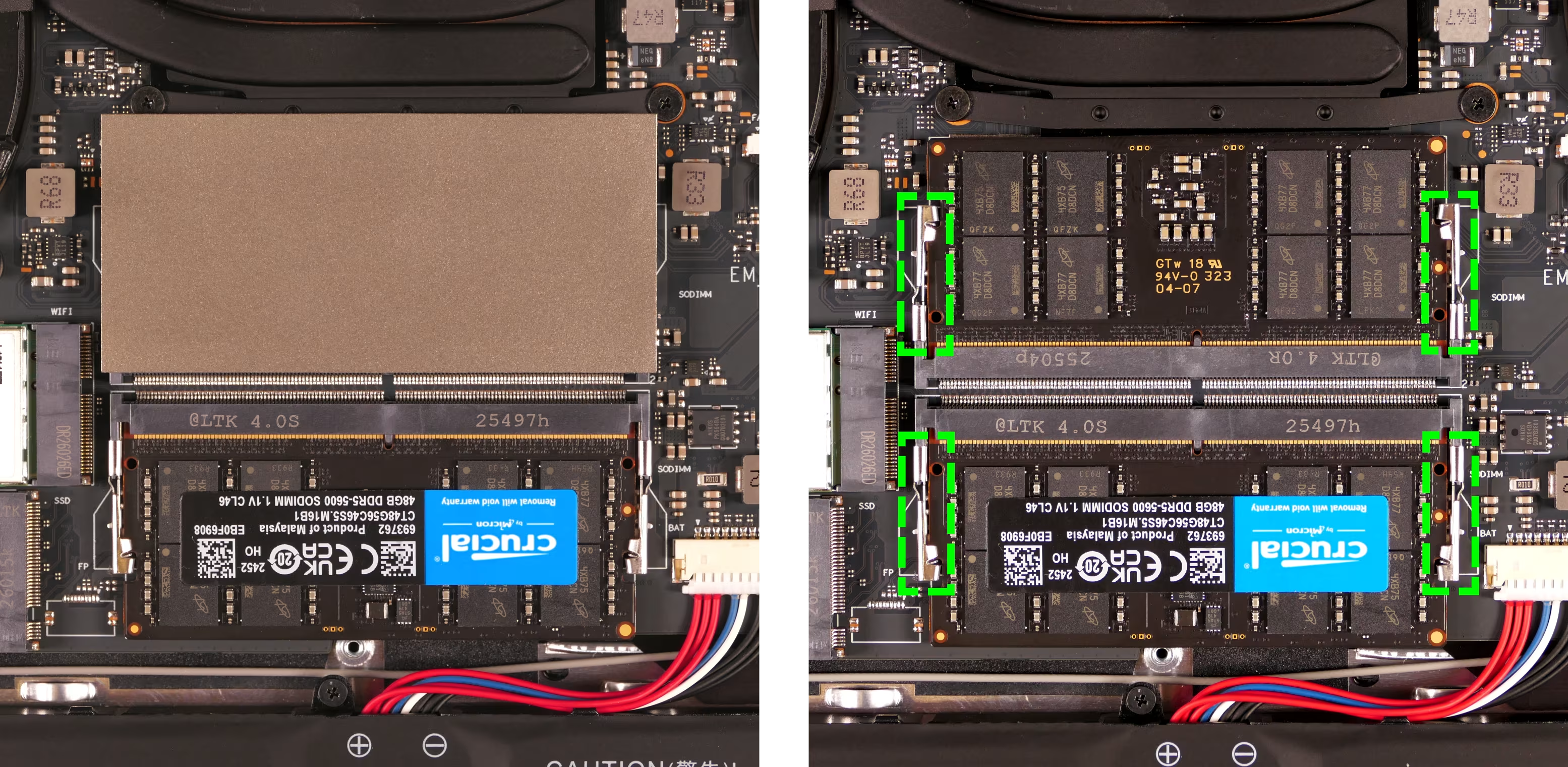
- Press the small tabs on both sides of the RAM simultaneously. The RAM should spring up to an angle.
- Remove the RAM from the slot.
- Insert the new RAM (or reseat the existing RAM) by placing it into the keyed slot and pressing down until it clicks into place.
- Optionally, replace any protective covers.
Replacing an M.2/NVMe SSD:
This model supports two M.2 SSDs. Both slots support PCIe NVMe Generation 4 connections and M.2 size 2280.
Tools required: Cross-head (Phillips) screwdriver
Time estimate: 3 minutes
Difficulty: Easy ●
Steps to replace the M.2 drive:
- Follow the steps above to remove the bottom cover.
- Unscrew the retainer screw opposite the M.2 slot.
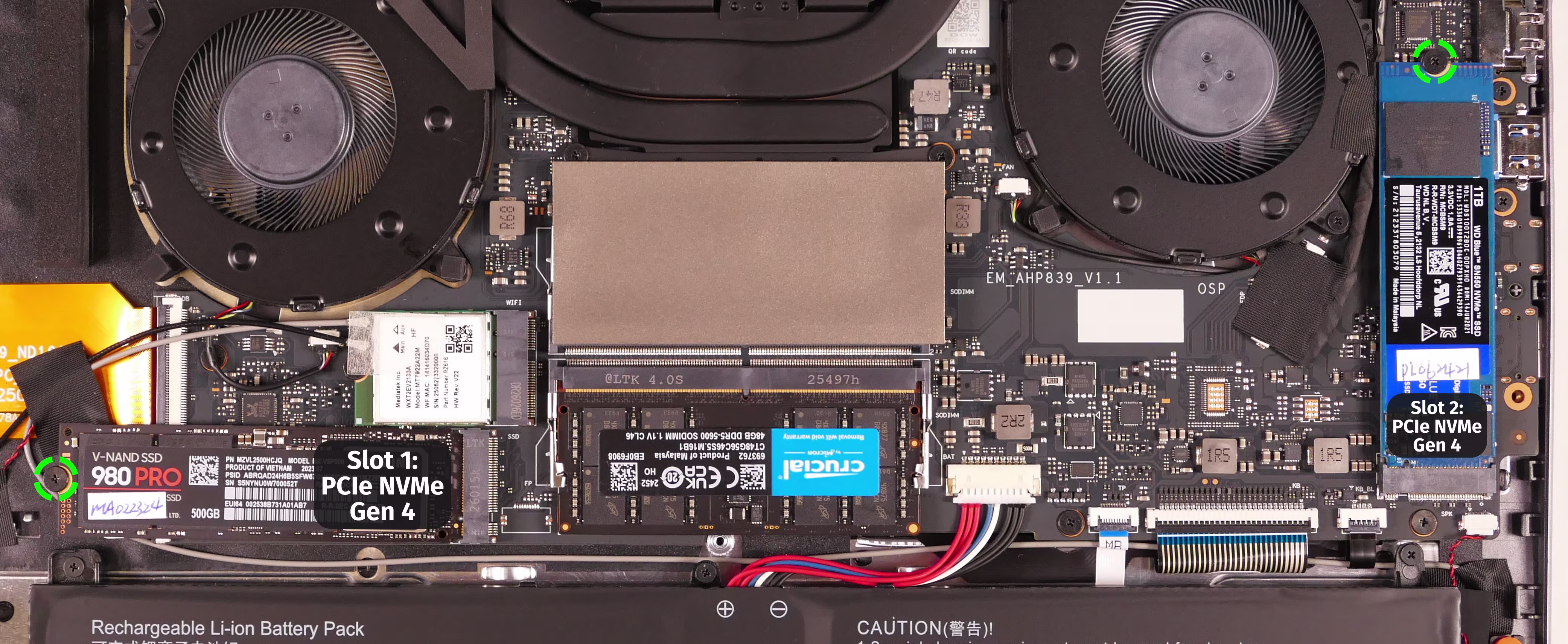
- Remove the existing M.2 drive by pulling it out of the slot.
- If replacing an M.2 drive, slowly peel any installed thermal pad (not pictured) off of the old drive, then place it on the new drive.
- If you ordered less than two drives when purchasing your system, an additional thermal pad will be included in the box.
- M.2 thermal pads are optional, and drives can be used without thermal pads if the pads are lost or unable to be transferred. Without the thermal pad, performance may be throttled to avoid overheating.
- Insert the new M.2 drive into the slot and hold it in place.
- Due to manufacturing tolerances, the M.2 drive may not sit perfectly straight within the slot when aligned with the retainer screw.
- Replace the retainer screw.
Replacing the battery:
The battery provides primary power whenever the system is unplugged.
Because the Pangolin Pro 16 doesn’t have a CMOS battery, the main battery is also used to power the RTC (real-time clock) and the memory storing the UEFI setup (BIOS) settings. A small amount of power is reserved for this function even when the system powers off due to low battery.
Part numbers:
- The battery’s model number is
4058C4-4S, and the original part number is4ICP4/58/125.- Third-party battery sellers may list one or both of these numbers, and may offer other compatible part numbers with the same model number.
- You can also contact System76 to purchase a replacement battery.
Tools required: Cross-head (Phillips) screwdriver
Time estimate: 10 minutes
Difficulty: Easy ●
Steps to replace the battery:
- Follow the steps above to remove the bottom cover.
- Remove the five battery screws, highlighted yellow below.
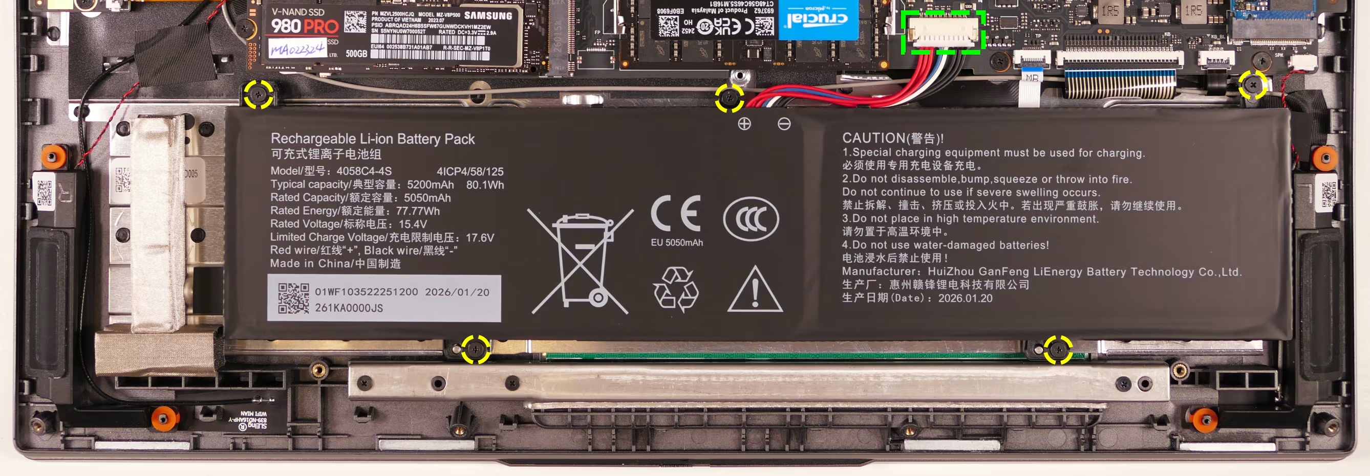
- Unplug the battery connector (highlighted green above) and lift the battery out of the chassis.
- If you’re intentionally resetting the CMOS, open the lid of the machine and hold down the power button for a few seconds to drain any residual energy.
- Place the new battery (or replace the existing battery) into the chassis.
- Plug in the battery.
- The red wires go on the left, and the black wires go on the right.
- Screw in the five battery screws.
- Reinstall the bottom cover.
Replacing the wireless card:
Your Pangolin’s WiFi and Bluetooth are both handled by the same module. It is a standard M.2 2230 slot with PCIe and USB interfaces (E-key).
Part numbers:
- The standard wireless card is a Mediatek
MT7922A22M.
Tools required: Cross-head (Phillips) screwdriver
Time estimate: 12 minutes
Difficulty: Medium ●
Steps to replace the WiFi/Bluetooth module:
- Follow the steps above to remove the bottom cover.
- Locate the wireless module. Peel back the clear tape securing the antenna wires to the card.
- As shown below, the wireless card’s label may stick to the tape; pull slowly and evenly to avoid ripping the label.
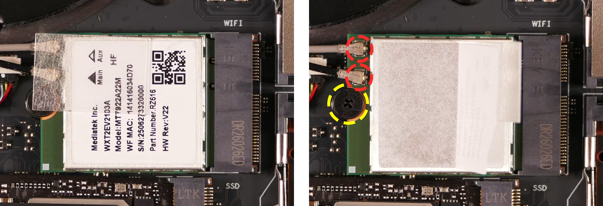
- Gently remove the two antennas (highlighted red above) by pulling them up and away from the wireless card.
- Remove the retaining screw opposite the M.2 slot, highlighted yellow above.
- The wireless card will pop up at an angle. Remove the card from the M.2 slot.
- Insert the new wireless card into the M.2 slot at an angle.
- Replace the retaining screw.
- Attach the two antennas by aligning the circular fittings and pressing onto the wireless card. The connectors will snap into place. Use caution when attaching the connectors; the pins can bend, break, or snap.
Replacing the cooling system:
The Pangolin Pro 16 has a fan and heatsink assembly to cool the CPU. The fans and heatsink are held together with adhesive; it is possible to replace the fans individually, but removing the entire assembly is recommended to perform service.
If a fan becomes noisy and cleaning it out doesn’t fix the issue, you may need a new fan. Contact support to start a warranty claim or parts purchase.
Depending on your climate and the age of the machine, it may be necessary to apply new thermal paste between the CPU and the heatsink. Thermal paste helps facilitate effective heat transfer between the CPU and the cooling equipment.
Part numbers:
- The left fan is a Yingfan
D85 NB700805HHT4B10003. - The right fan is a Yingfan
D86 NA700805HHT4B10003.
Tools required: Cross-head (Phillips) screwdriver, thermal paste
Time estimate: 20 minutes
Difficulty: High ●
Steps to replace the fan/heatsink/thermal paste:
- Follow the steps above to remove the bottom cover.
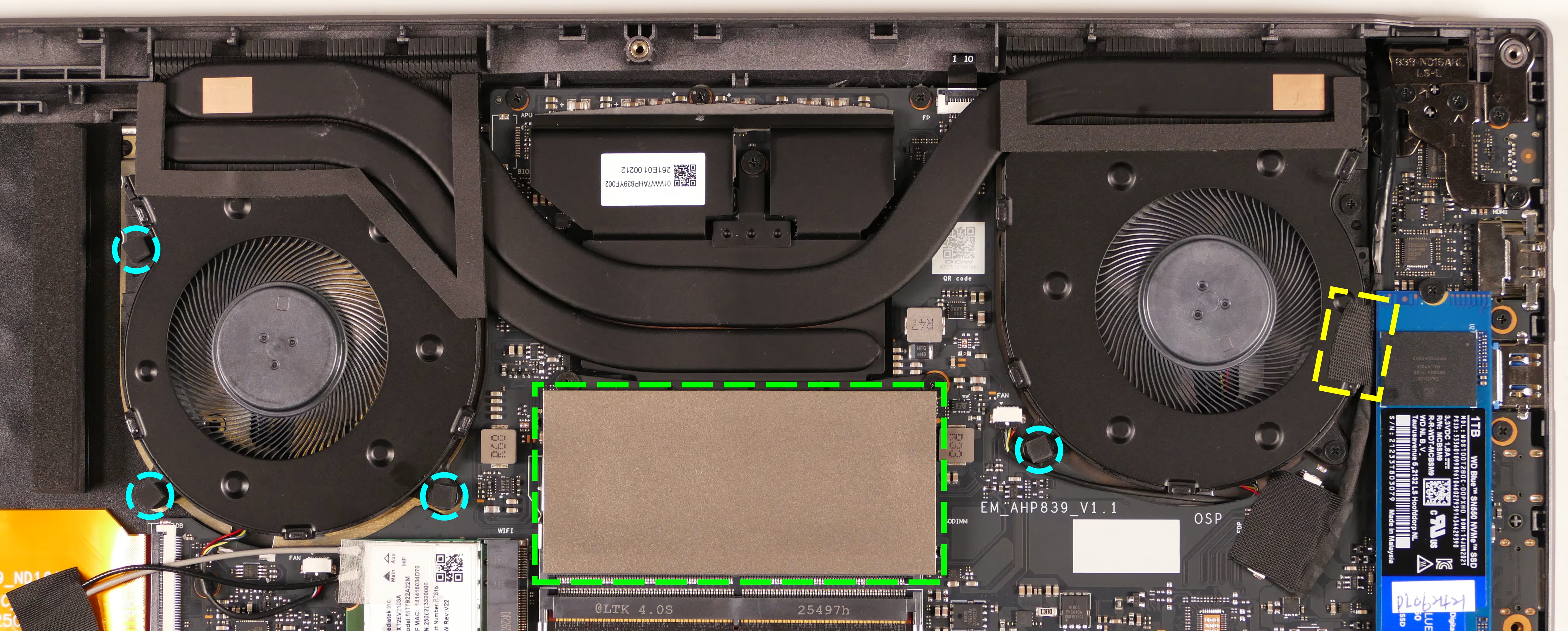
- Remove the black spacer cubes covering any of the six fan screws (three per fan).
- In the below photo, four screws are covered.
- Remove the cover from the top RAM slot and peel back the black tape holding the LCD cable to the left fan (pictured on the right).
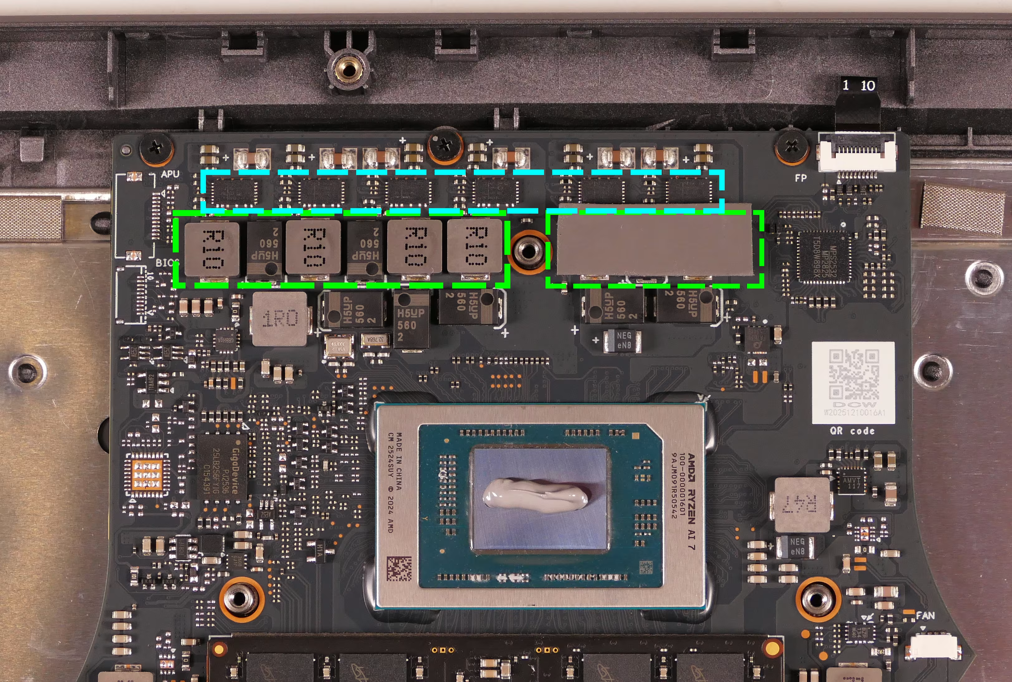
- Remove the six fan screws, highlighted cyan below.
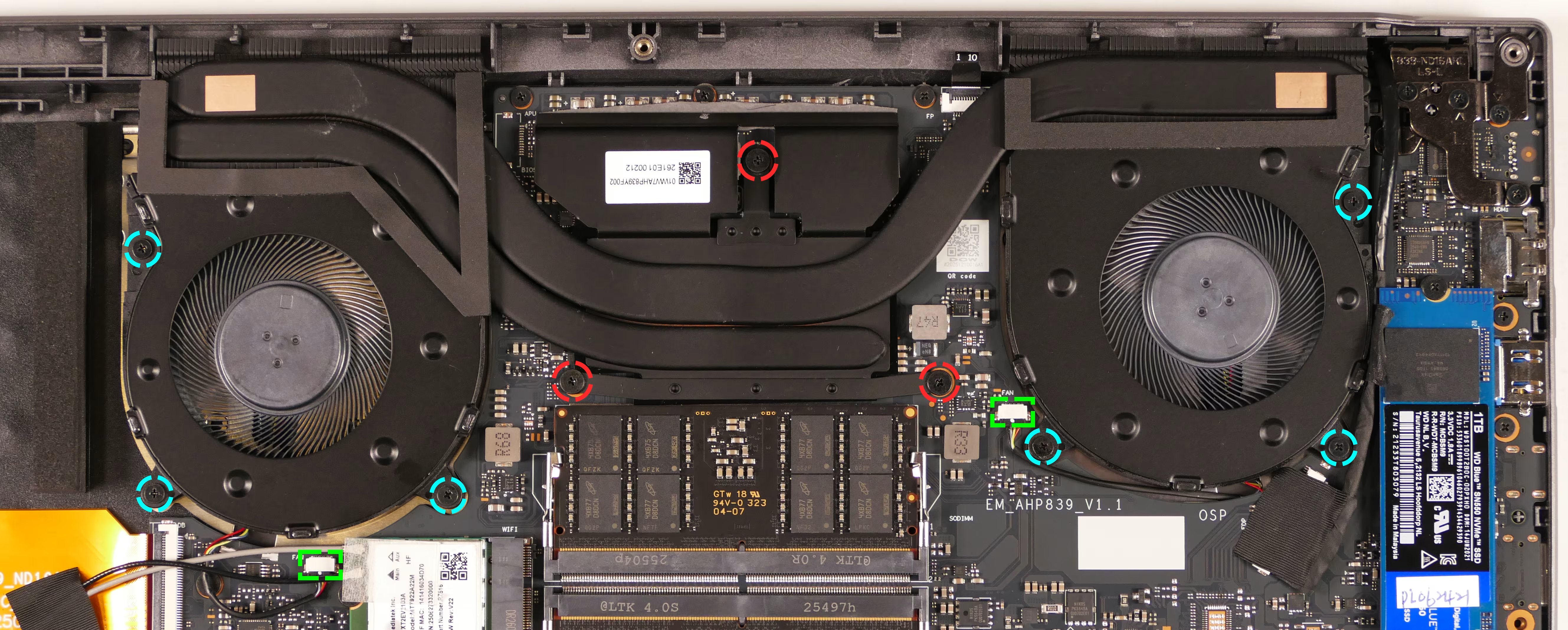
- Unplug the two
FANconnectors, highlighted green above. - Unscrew the three heatsink screws, highlighted red above.
- The heatsink screws are held captive and will not come out of the heatsink.
- Remove the fan and heatsink assembly from the system, being careful not to bend the heatsink pipe. It may take some pressure to break the seal of the thermal paste.
- The fans are held onto the heatsink with adhesive strips on the top side; if they come loose, place them back into position after reinstalling the heatsink.
- Using a paper towel, remove the existing thermal paste from the CPU chip and the heatsink. You may also use a small amount of rubbing alcohol if the old paste is dried or difficult to remove.
- Any thermal pad strips don’t need to be removed.
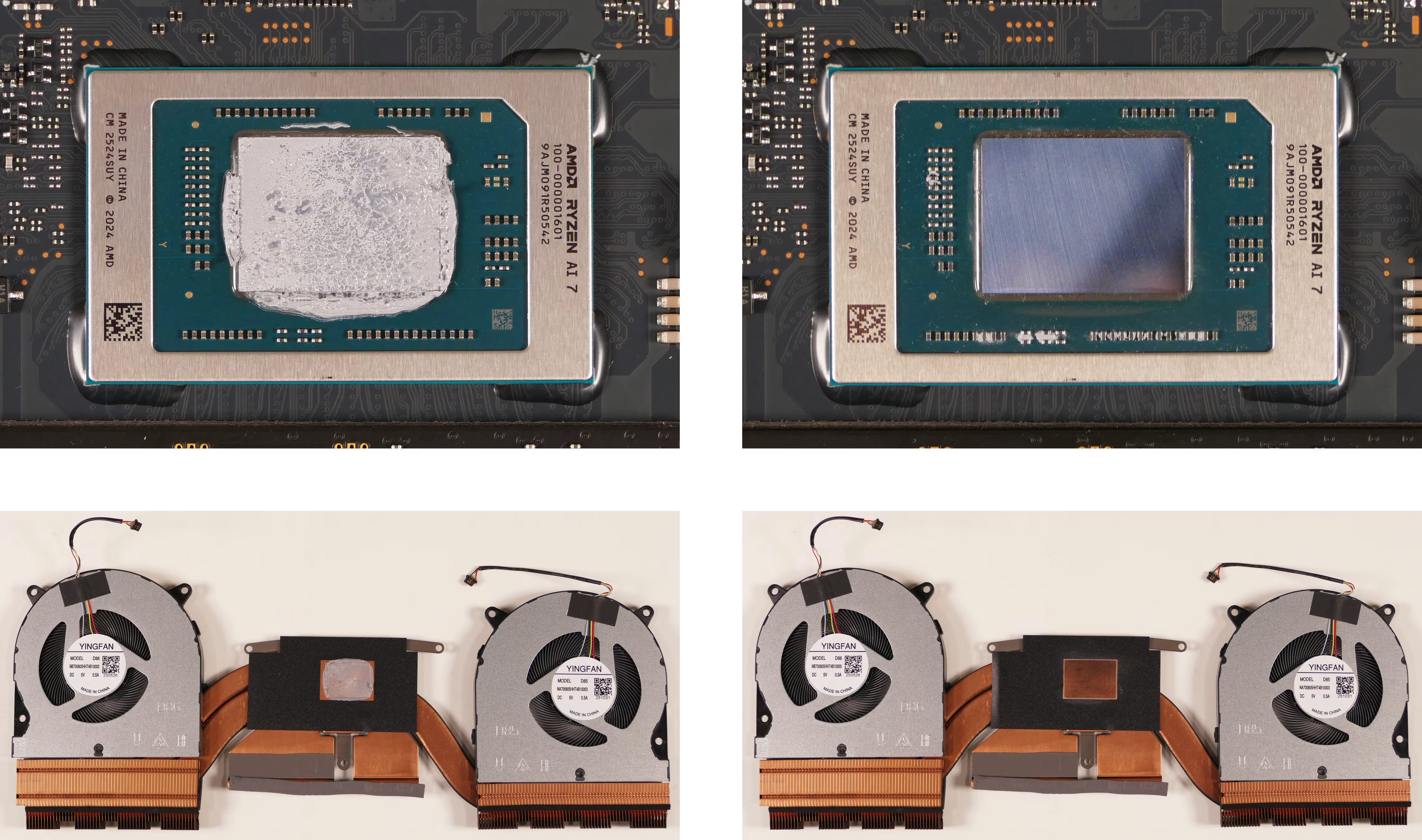
- After cleaning the CPU and heatsink, apply a small line of thermal paste directly onto the CPU chip.
- Also place any thermal pad strips back into position if they came loose while removing the heatsink.
- The wider two thermal pads cover the
R10chips or the corresponding positions on the heatsink. - The thinner thermal pad covers the six smaller chips (farther from the CPU than the
R10chips) or the corresponding position on the heatsink.
- The wider two thermal pads cover the
- Also place any thermal pad strips back into position if they came loose while removing the heatsink.
- Carefully replace the heatsink.
- To align the screw holes correctly, fit the gaps in the heatsink fins around the corresponding tabs sticking off the vents on the back of the chassis.
- Reinstall the three heatsink screws.
- Reinstall the six fan screws and plug in the two fan connectors.
- The wire for the fan near the wireless card runs under the wireless card’s antennas.
- Stick the black spacer cubes back onto the fan screws, the black tape back onto the LCD cable, and the silver cover back onto the top RAM slot.
- Replace the bottom panel.
Replacing the speakers:
The system has two speakers, which can be replaced independently.
Tools required: Cross-head (Phillips) screwdriver
Time estimate: 10 minutes
Difficulty: Medium ●
Steps to replace the speakers:
- Follow the steps above to remove the bottom cover.
- For the right speaker, also remove the SSD from slot 1.
- Unplug the
SPKconnector for each of the speakers, highlighted cyan below.- For the right speaker (pictured on the left), peel back the black tape and white sticker covering the speaker wire.
- This can alternatively be done after freeing the speakers.
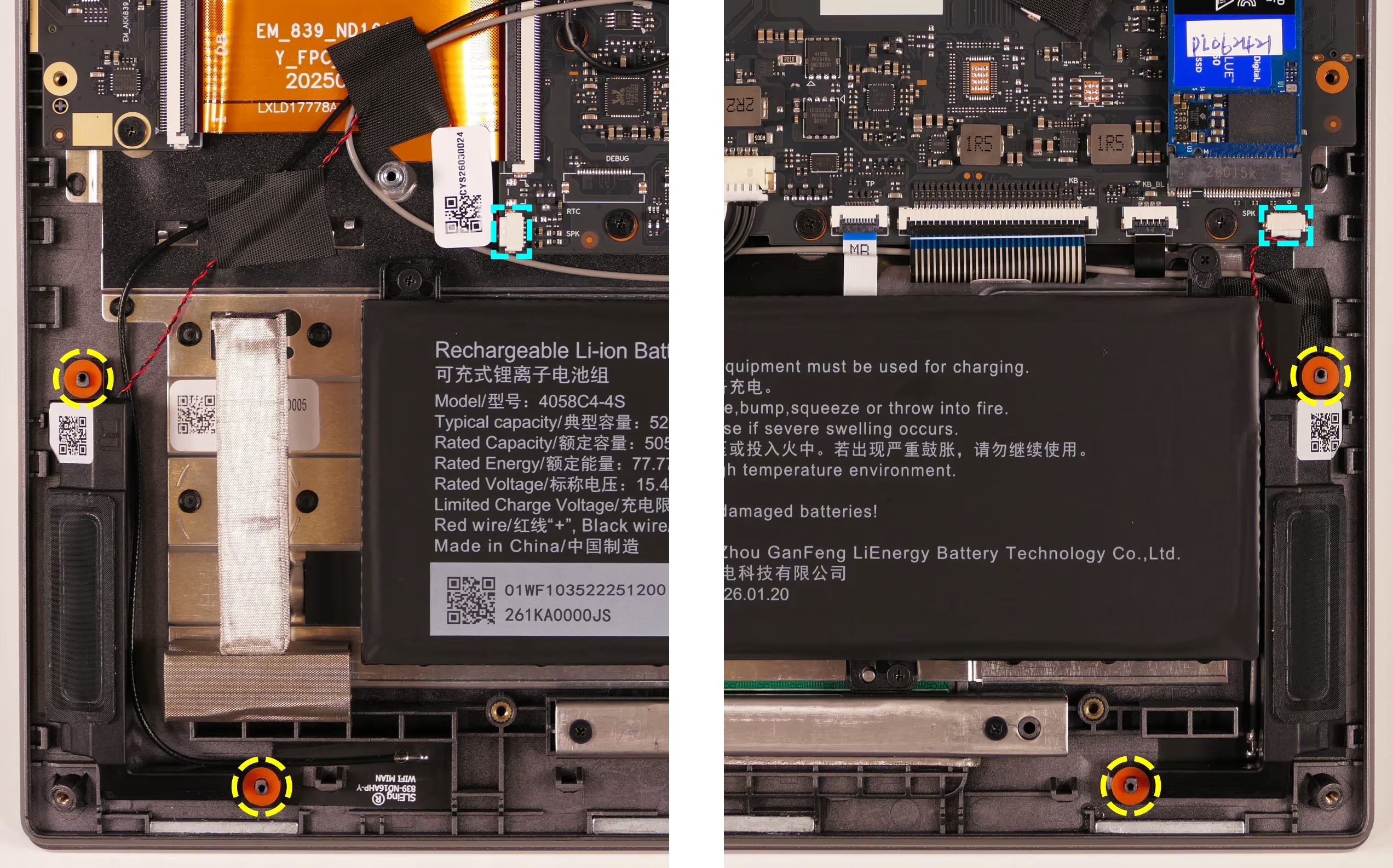
- Pull the speakers off of the plastic mounting posts (highlighted yellow above), then lift the speakers out of the machine.
- Slide the new speakers onto the plastic posts and connect the corresponding
SPKconnectors. - Replace the tape and sticker (for the right speaker) and the bottom panel.